Eureka AIR delivers breakthrough ideas for toughest innovation challenges, trusted by R&D personnel around the world.

Transformer switch oil tank structure and transformer

A technology for switching oil tank and transformer oil, applied in the direction of transformer/inductor cooling, transformer, variable transformer, etc., can solve the problems of complex lead layout, difficult to guarantee insulation, large transformer volume, etc., to expand the scope of application and avoid disadvantages Influence and improve the effect of insulation level

Inactive Publication Date: 2018-10-16
江苏鑫航电力设备工程有限公司
View PDF0 Cites 0 Cited by
  • Summary
  • Abstract
  • Description
  • Claims
  • Application Information

AI Technical Summary

Problems solved by technology

[0003] This structure makes the entire transformer larger in size and higher in cost, and the layout of the capacity regulating (voltage regulating) switch and the lead wires of the transformer is more complicated. Especially for large-capacity transformers, the lead wires are thicker and larger, which makes the layout in a limited oil tank very tense. Insulation is difficult to guarantee

Method used


Image

  • Transformer switch oil tank structure and transformer
  • Transformer switch oil tank structure and transformer
  • Transformer switch oil tank structure and transformer

Examples


Embodiment Construction

[0044] The following will clearly and completely describe the technical solutions in the embodiments of the present invention with reference to the accompanying drawings in the embodiments of the present invention. Obviously, the described embodiments are only some, not all, embodiments of the present invention. The components of the embodiments of the invention generally described and illustrated in the figures herein may be arranged and designed in a variety of different configurations. Accordingly, the following detailed description of the embodiments of the invention provided in the accompanying drawings is not intended to limit the scope of the claimed invention, but merely represents selected embodiments of the invention. Based on the embodiments of the present invention, all other embodiments obtained by those skilled in the art without making creative efforts belong to the protection scope of the present invention.

[0045] At present, the capacity adjustment (voltage ad...


PUM


Abstract

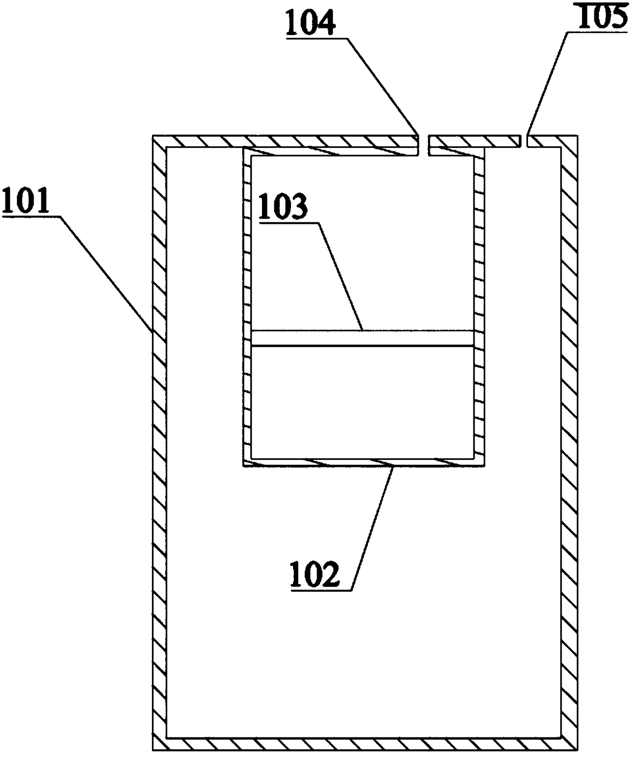
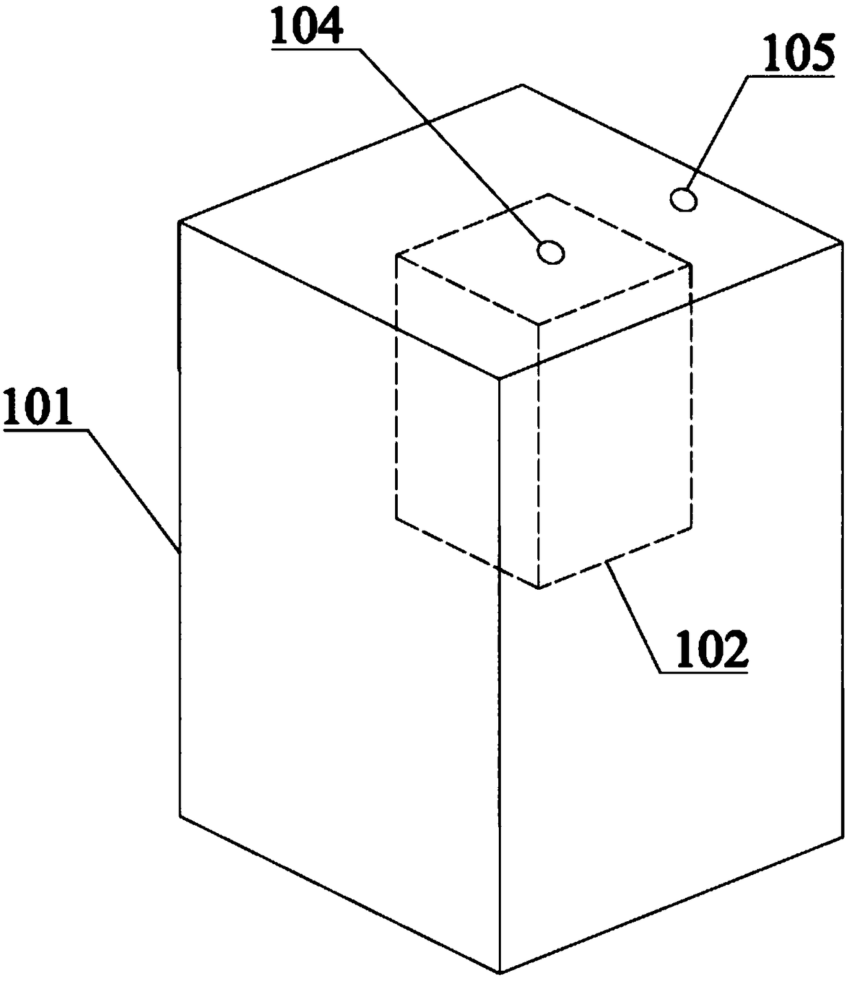
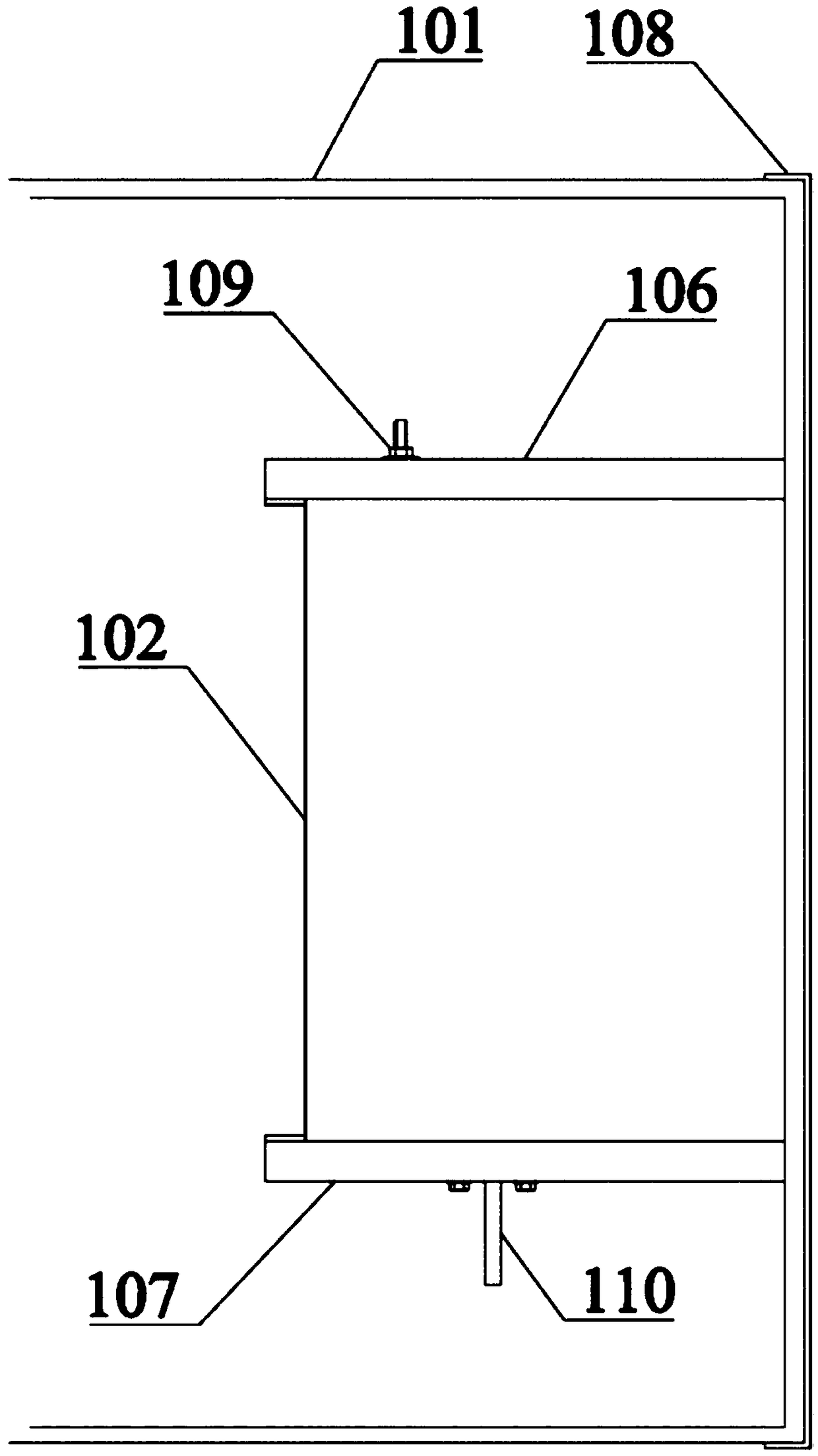
The invention provides a transformer switch oil tank structure and a transformer, and relates to the field of electrical equipment. The transformer switch oil tank structure comprises a transformer oil chamber, a switch oil chamber and a transformer switch. The transformer switch is placed in the switch oil chamber, the switch oil chamber is placed in the transformer oil chamber, and the top wallof the switch oil chamber is connected to the inner side of the top wall of the transformer oil chamber and connected to the middle position of the top wall of the transformer oil chamber. The transformer switch is flat and placed horizontally in the switch oil chamber. According to the transformer switch oil tank structure, the switch oil chamber is added in the transformer oil chamber, so that the switch oil chamber is separated from the transformer oil chamber. At the same time, the flat transformer switch is adopted, so that the switch oil chamber can utilize the space in the transformer oil chamber more effectively. A lead is reasonably stretched in layout, the transformer insulation level is improved, the transformer cost is reduced, and the application range of the transformer is expanded.

Description

technical field [0001] The invention relates to the field of electrical equipment, in particular to a transformer switch oil tank structure and a transformer. Background technique [0002] At present, the capacity adjustment (voltage adjustment) switch commonly used in transformers is generally a tumbler structure, the static contact is installed on the circumference of the tumbler, the moving contact is fixed on the support of the middle main shaft, and the tumbler is formed into an independent oil chamber. The (voltage regulating) switch is vertically arranged on the side wall of the transformer, and the motor is arranged on the top of the transformer; it is connected with the winding taps and the incoming and outgoing lines of the transformer through connecting wires. [0003] This structure makes the entire transformer larger in size and higher in cost, and the layout of the capacity regulating (voltage regulating) switch and the lead wires of the transformer is more com...

Claims


Application Information

Patent Timeline
Patent Type & Authority Applications(China)
IPC IPC(8): H01F27/14H01F27/40H01F29/04
CPCH01F27/14H01F27/40H01F29/04
Inventor 刘英
Owner 江苏鑫航电力设备工程有限公司
Why Eureka
Eureka Blog
Learn More