
Wafer clamping assembly and method for clamping wafer

A wafer and fixture technology, applied in electrical components, semiconductor/solid-state device manufacturing, circuits, etc., can solve the problems of the wafer 10 being bounced, unable to effectively align and pick up the wafer, etc., and achieve the effect of rapid movement and rotation

Inactive Publication Date: 2018-10-16
HIMAX TECH LTD
View PDF13 Cites 0 Cited by
  • Summary
  • Abstract
  • Description
  • Claims
  • Application Information

AI Technical Summary

Problems solved by technology

However, the conventional meshing fork cannot move and rotate quickly, thus causing the wafer 10 to bounce off
[0005] In view of the fact that traditional mechanical forks cannot effectively align and pick up wafers, it is urgent to propose a novel wafer fixture to improve the shortcomings of traditional mechanical forks

Method used


Image

  • Wafer clamping assembly and method for clamping wafer
  • Wafer clamping assembly and method for clamping wafer
  • Wafer clamping assembly and method for clamping wafer

Examples


Embodiment Construction

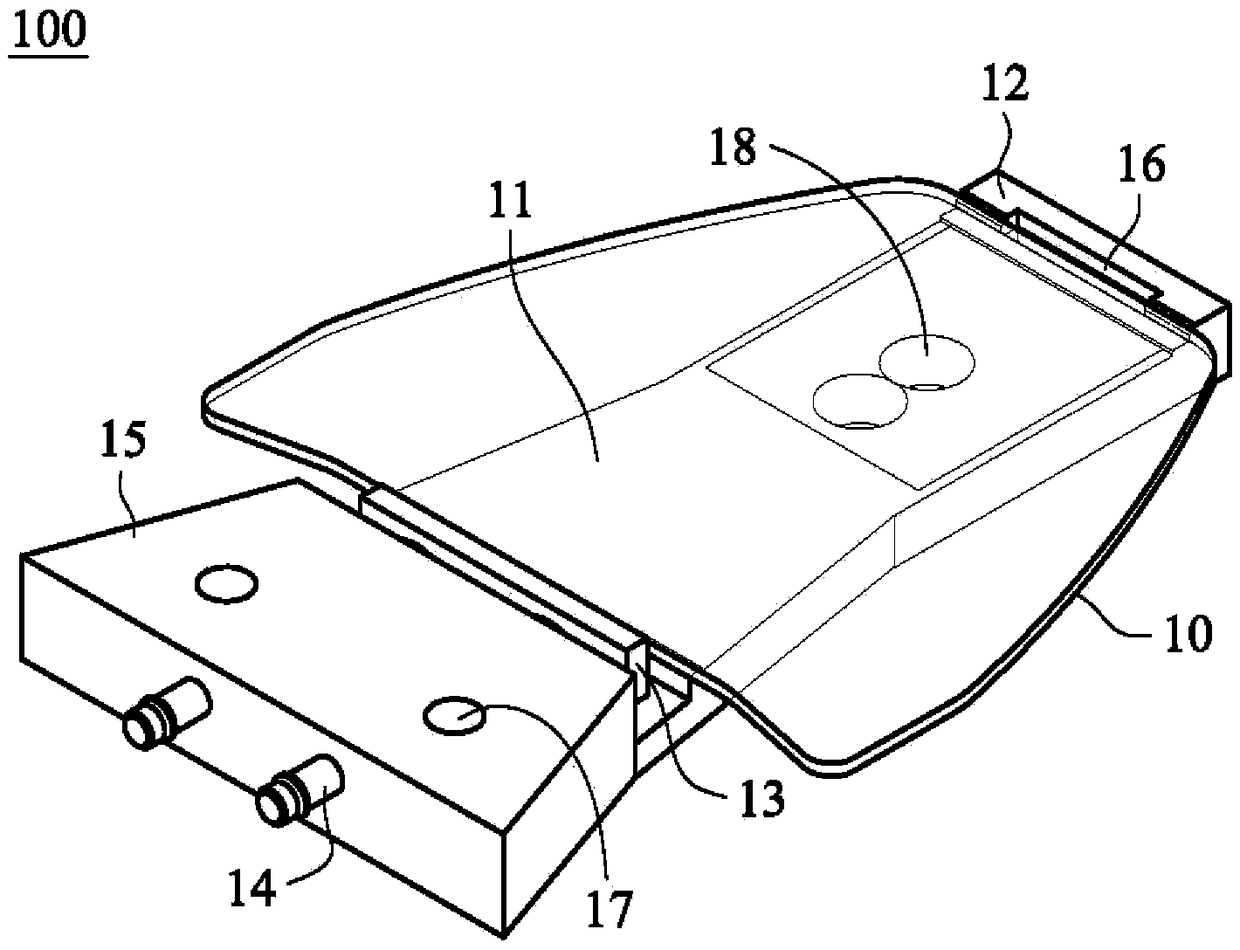
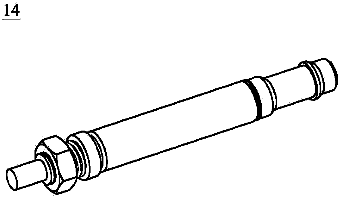
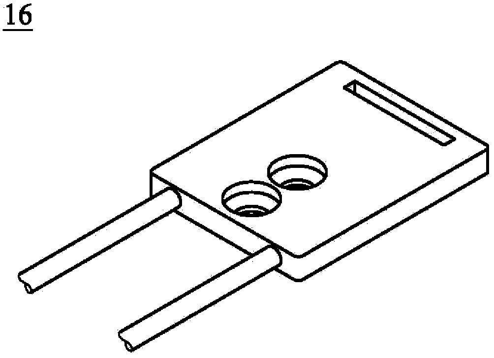
[0030] Figure 1A A perspective view of a wafer holder 100 suitable for a robotic system according to an embodiment of the present invention is shown. figure 2 show Figure 1A A top view of the wafer holder 100. The wafer holder 100 of this embodiment can temporarily hold the wafer 10 at a fixed position to avoid movement or separation. The wafer holder 100 is specifically (but not limited) used to hold a wafer without touching the top or bottom of the wafer. When the wafer holder 100 is used as a manipulator to cooperate with other components of the robot system to pick up and place the wafer 10 (such as optical lens or glass), the wafer holder 100 can also be called a robot fork.

[0031] In this embodiment, the wafer holder 100 may include a platform 11 having a flat top surface. The platform 11 is located under the wafer 10 for supporting the wafer 10 .

[0032] The wafer holder 100 of this embodiment may include a stopper 12 disposed on the front end of the platform 1...


PUM


Abstract

The invention provides a wafer clamping assembly and a method for clamping a wafer, wherein the wafer clamping assembly comprises a platform having a top surface, a stopper arranged at a front end ofthe platform, a push rod arranged at a rear end of the platform, at least an actuator pivotally connected to the push rod; and a sensor arranged at the front end of the platform for measuring the distance between the sensor and the wafer thereon.

Description

technical field [0001] The present invention relates to a wafer clamp, in particular to a wafer clamp suitable for a robot system for picking up and placing wafers. Background technique [0002] A robotic hand or fork of a robotic system is commonly used to automatically pick up and place wafers (wafers or chips). Conventional robotic systems use vacuum forks to hold the wafer. Because the traditional vacuum fork is prone to misalignment, the wafer cannot be accurately aligned and picked up, causing the wafer to drop and break. [0003] In addition, conventional vacuum forks are designed to contact either the top or bottom surface of the wafer to be picked up. Such devices cannot be applied to some wafers, such as optical components (such as optical lenses or glass). [0004] In view of this, an engaged tooth fork is proposed to improve the lack of vacuum tooth fork. However, the conventional meshing fork cannot move and rotate quickly, thus causing the wafer 10 to bounc...

Claims


Application Information

Patent Timeline
Patent Type & Authority Applications(China)
IPC IPC(8): H01L21/687
CPCH01L21/687
Inventor 卢芳万张瑞堂
Owner HIMAX TECH LTD
Learn More