Sweeping robot

A sweeping robot and main machine technology, applied in the direction of cleaning carpets, floors, machine parts, etc., can solve the problems that ground stains cannot be removed, increase the range of suction, and the cleaning body has a short air intake distance, so as to reduce indoor air secondary Pollution, increasing the range of suction, and simplifying the structure

Inactive Publication Date: 2018-10-19
阳珉
View PDF1 Cites 5 Cited by
  • Summary
  • Abstract
  • Description
  • Claims
  • Application Information

AI Technical Summary

Problems solved by technology

[0006] The beneficial effects of the present invention mainly lie in that: the two installation disks with opposite rotation directions can overcome the torsion force generated by the friction between the cleaning head and the ground under the installation disk. The bottom surface can wipe the surface to be cleaned. The radially extending cleaning body has the shortest air intake distance and small air intake resistance. The side edge of the cleaning body has a scraping effect on the surface to be cleaned, which can overcome the rotation of the side brush and pump the ground. , It is easy to raise dust fluff, and it is impossible to remove the ground stains. The contact part between the cleaning head and the ground has no rotating shaft, and the hair will not be entangled. In addition, it can reduce the indoor air secondary pollution caused by fine dust; the semi-enclosed dust suction air duct formed by the space between the adjacent cleaning body, the upper cover, and the surface to be cleaned is in a rotating state during operation, which increases the range of suction. At the same time, it has a small air intake area, small air intake resistance, and only a small suction force can suck the dirt into the suction hole; the sweeping and dragging functions can be realized through the cleaning head, realizing the integration of sweeping, dragging and suction

Method used


Image

  • Sweeping robot
  • Sweeping robot
  • Sweeping robot

Examples


Embodiment 1

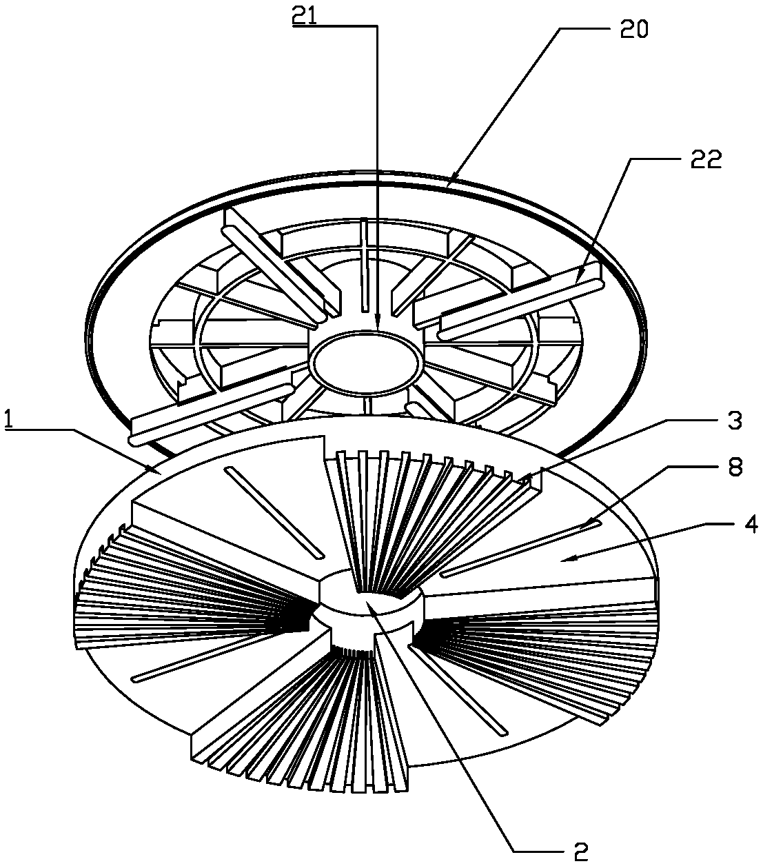
[0028] Embodiment 1: as figure 1 , figure 2 , image 3 , Figure 4 As shown, a preferred embodiment of the present invention includes a main machine 10, a dust suction device 26 arranged inside the main machine, two mounting plates 20 with opposite rotation directions arranged below the main machine, and a hollow The central shaft 21, the upper end of the central shaft 21 passes through the bottom shell of the main machine 10 and enters the interior of the main machine 10, and communicates with the dust suction device 26 through two non-rotating dust suction pipes 25, and the two dust suction pipes 25 can be inserted respectively In the inner cavities of the two central shafts 21, sliding bearings can be arranged at the connection between the rotating central shaft 21 and the static suction pipe 25, which can reduce friction and dynamic sealing. On the outer periphery of the upper end of the central shaft 21, a bearing The plane thrust bearing 24 of axial load, the motor 1...

Embodiment 2

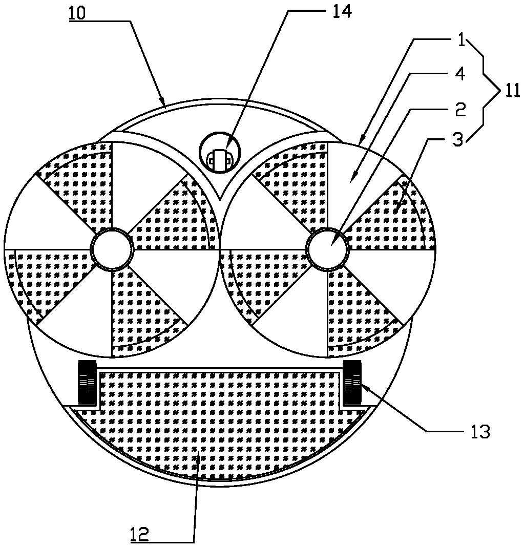
[0029] Embodiment 2: as Figure 5 As shown, a preferred embodiment of the present invention includes a main machine 10, two cleaning heads 11 installed below the mounting plate and rotating in opposite directions are arranged under the main machine 10, the cleaning heads 11 include an upper cover 1, the A dust suction hole 2 is provided at the center of the upper cover 1, and a plurality of radially extending and downwardly protruding cleaning bodies 3 are provided at intervals around the bottom of the upper cover 1 with the dust suction hole 2 as the center. The cleaning body 3 is made of flexible wiping material. The lower surface of the cleaning body 3 is in contact with the surface to be cleaned. The motor in the main machine drives the mounting plate to drive the cleaning head 11 on the mounting plate to rotate. The cleaning head 3 wipes the surface to be cleaned in a rotating manner. On the cleaning surface, the space between the adjacent cleaning body 3 and the upper co...

Embodiment 3

[0030] Embodiment 3: as Figure 6 , Figure 7 As shown, a preferred embodiment of the present invention comprises a main frame 10, two cleaning heads 11 installed below the mounting plate below the main frame 10, and each of the two mounting plates is driven by a stepping motor to drive the cleaning head 11 below the mounting plate. The head 11 rotates. When the rotation speeds of the two cleaning heads are different, the cleaning head with a faster rotation speed will rotate relative to the cleaning head with a slower rotation speed. While sweeping the ground and vacuuming, the main machine can twist and move or turn, canceling the walking wheels and universal wheels usually used by sweeping robots.

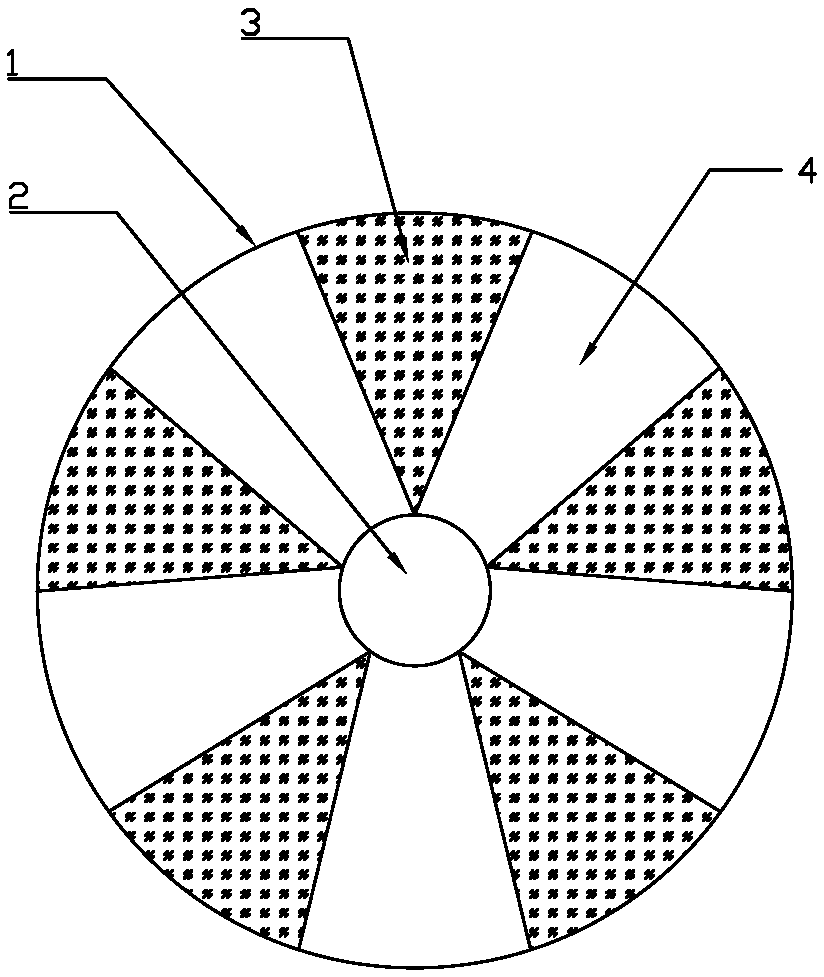
[0031] In a preferred embodiment of the present invention, the cleaning head is as Figure 9 , Figure 10 As shown, the upper cover 1 is included, and the central position of the upper cover 1 is provided with a dust suction hole 2, and the bottom of the upper cover 1 is cent...


PUM


Abstract

The invention discloses a sweeping robot. The sweeping robot comprises a main machine, a dust collection device and two installation disks, wherein the dust collection device is arranged at the innerpart of the main machine; the two installation disks are arranged under the main machine and are in opposite rotating directions; hollow central shafts are arranged at the central parts of the installation disks; detachable cleaning heads are arranged under the installation disks; each cleaning head comprises an upper cover; dust collection holes matched with a dust collection pipe are formed in the central parts of the upper covers; a plurality of cleaning bodies stretching to a radial direction and protruding downwards are circumferentially arranged under the upper covers at intervals by taking the dust collection holes as centers; the lower surfaces of the cleaning bodies are in contact with a cleaned surface, and the cleaned surface can be swept in a rotating way; a dust collection airduct is formed by space among adjacent cleaning bodies, the corresponding upper cover and the cleaned surface; dirt can be sucked into the dust collection holes through the dust collection air ductsand then can be sucked into the dust collection device through the central shafts. The sweeping robot disclosed by the invention has the characteristics that sweeping, mopping and sucking are integrated, time and labor are saved, and a cleaning effect is good.

Description

technical field [0001] The present invention relates to the field of cleaning tools, in particular to a sweeping robot (also called an intelligent vacuum cleaner). Background technique [0002] In the prior art, household sweeping robots usually use side brushes and roller brushes to sweep the floor, and the vacuum port to vacuum for cleaning. However, the side brushes and roller brushes are only suitable for sweeping the floor, and cannot mop the floor, and cannot remove stubborn stains and sewage on the ground. . In addition, the side brush rotates and beats the ground, which can easily cause dust flakes to fly, causing secondary pollution of the indoor air, and it is easy to sweep the granular garbage everywhere. Small suction power increases the noise of vacuuming, and during daily use, the hair is easily entangled on the side brush and roller brush, which not only affects the cleaning effect, but may also cause the main unit to be unusable or even damaged. [0003] An...

Claims


Application Information

Patent Timeline
Patent Type & Authority Applications(China)
IPC IPC(8): A47L11/282A47L11/40
CPCA47L11/282A47L11/40A47L11/4038A47L11/4069A47L11/4094
Inventor 阳珉
Owner 阳珉
Why Eureka
Try Eureka