Linkage receiving mechanism of punch press

A punching machine and feeding chute technology, applied in metal processing equipment, stripping devices, manufacturing tools, etc., can solve the problems of high labor intensity and insecurity, and achieve the effect of high work efficiency, low cost and good safety.

Pending Publication Date: 2018-10-19
苏州市华能发电机有限公司
View PDF7 Cites 1 Cited by
  • Summary
  • Abstract
  • Description
  • Claims
  • Application Information

AI Technical Summary

Problems solved by technology

[0003] The technical problem to be solved by the present invention is to provide a material receiving mechanism to solve the labor-intensive and unsafe problems of manual material receiving after punching the stator and rotor blades, and improve work efficiency

Method used


Image

  • Linkage receiving mechanism of punch press
  • Linkage receiving mechanism of punch press

Examples


Embodiment Construction

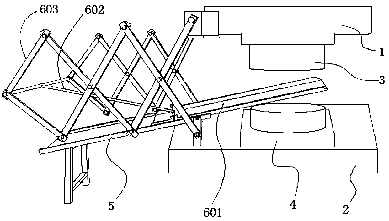
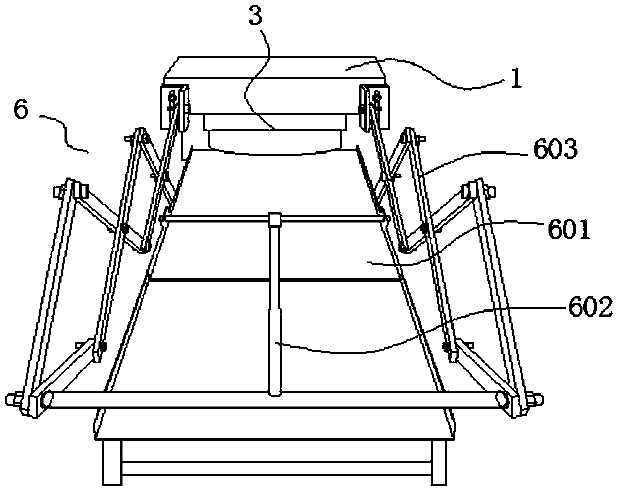
[0015] Such as figure 1 and 2 As shown, a punching machine linkage material receiving mechanism includes a chute 5, a material receiving hand 6, an upper die base 1 and a lower die base 2 arranged on the punch press, the upper die base 1 is provided with an upper die 3, and the lower die base 2 is provided with lower mold 4 correspondingly. The chute 5 is positioned at the left side of the lower die 4, the right end of the chute 5 is fixedly connected with the lower die base 2, and the left end is fixed on the ground by a support. Chute 5 is placed obliquely, and its left end is lower than the right end. The material receiving hand 6 is provided with a material receiving trough 601 , a traction arm 602 and two telescopic arms 603 . The two telescopic arms 603 are arranged symmetrically on both sides of the receiving trough 601, and each telescopic arm 603 is composed of two Z-shaped movable rods that are mirrored and intersected to form a network structure, passing through ...


PUM


Abstract

The invention discloses a linkage receiving mechanism of a punch press. The linkage receiving mechanism comprises a sliding chute, a receiving hand, an upper die base and a lower die base, wherein theupper die base and the lower die base are arranged on the punch press, an upper die is arranged on the upper die base, and a lower die is correspondingly arranged on the lower die base. The sliding chute is located on the left side of the lower die, the right end of the sliding chute is fixedly connected with the lower die base, and the left end of the sliding chute is lower than the right end thereof. The receiving hand is provided with a receiving groove, a traction arm and two telescopic arms, the two telescopic arms are symmetrically arranged on the two sides of the receiving groove, eachtelescopic arm is composed of two Z-shaped movable rods, and every two movable rods are rotationally connected to form a net structure in a mirror-image crossing mode. Every two connected movable rods enable the corresponding telescopic arm to form one left end and two up and down right ends, and the upper right end of each telescopic arm is rotationally connected with the upper die base, and thelower right end of each telescopic arm is rotationally connected with the lower die base. The left end of the traction arm is connected with the left end of a movable arm; and the receiving groove isconnected to the sliding chute in a sliding mode, and the receiving groove is rotationally connected with the right end of the traction arm. The requirements of continuous receiving can be met, and the working efficiency is high.

Description

technical field [0001] The invention relates to the field of production and processing of stator and rotor slices, in particular to a punching machine linkage material receiving mechanism. Background technique [0002] In the field of production and processing technology of stator and rotor, the traditional method is to manually take the stator and rotor out of the raw material storage bin, and send it to the designated position on the punching machine for punching and shaping, and then move it to another punching machine for further punching Hole processing, and finally complete the finished production of stator and rotor blades. The above-mentioned traditional methods rely on manual feeding and retrieving of the stator and rotor blades. The labor intensity is high, the production efficiency is low, and it cannot meet the requirements of mass production, and the workers are prone to fatigue after working for a long time. It may lead to safety accidents such as work-related...

Claims


Application Information

Patent Timeline
Patent Type & Authority Applications(China)
IPC IPC(8): B21D45/08B21D28/14
CPCB21D28/14B21D45/08
Inventor 李玉军董永良
Owner 苏州市华能发电机有限公司
Why Eureka
Try Eureka