
Fixture for conveniently machining cylindrical parts

A part processing and fixture technology, which is applied in the field of fixtures that facilitate the processing of cylindrical parts, can solve the problems of low positioning efficiency of cylindrical parts, affecting the use of workers, inconvenient cylindrical parts, etc., and achieves the effects of convenient processing operation, simple structure and high practical performance.

Inactive Publication Date: 2018-10-19
柳州通亿汽车配件制造有限公司
View PDF4 Cites 13 Cited by
  • Summary
  • Abstract
  • Description
  • Claims
  • Application Information

AI Technical Summary

Problems solved by technology

[0003] At present, when processing cylindrical parts, workers generally fix the position of cylindrical parts manually, which is not convenient for stable clamping of cylindrical parts, and the positioning efficiency of cylindrical parts is low, which affects the use of workers. The jig used to solve the above problem

Method used


Image

  • Fixture for conveniently machining cylindrical parts
  • Fixture for conveniently machining cylindrical parts
  • Fixture for conveniently machining cylindrical parts

Examples


Embodiment

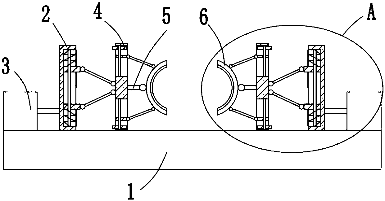
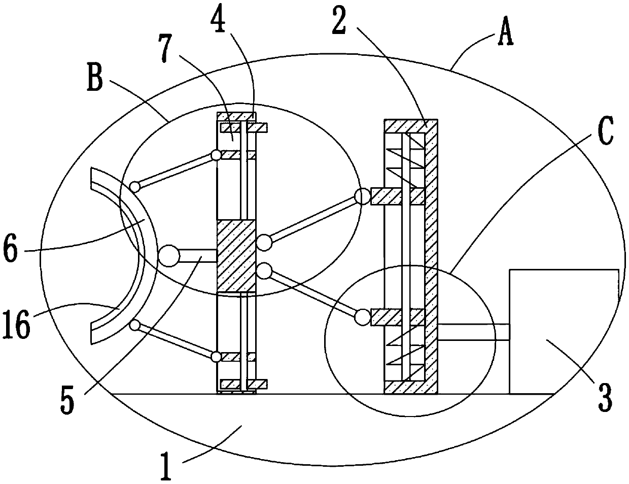
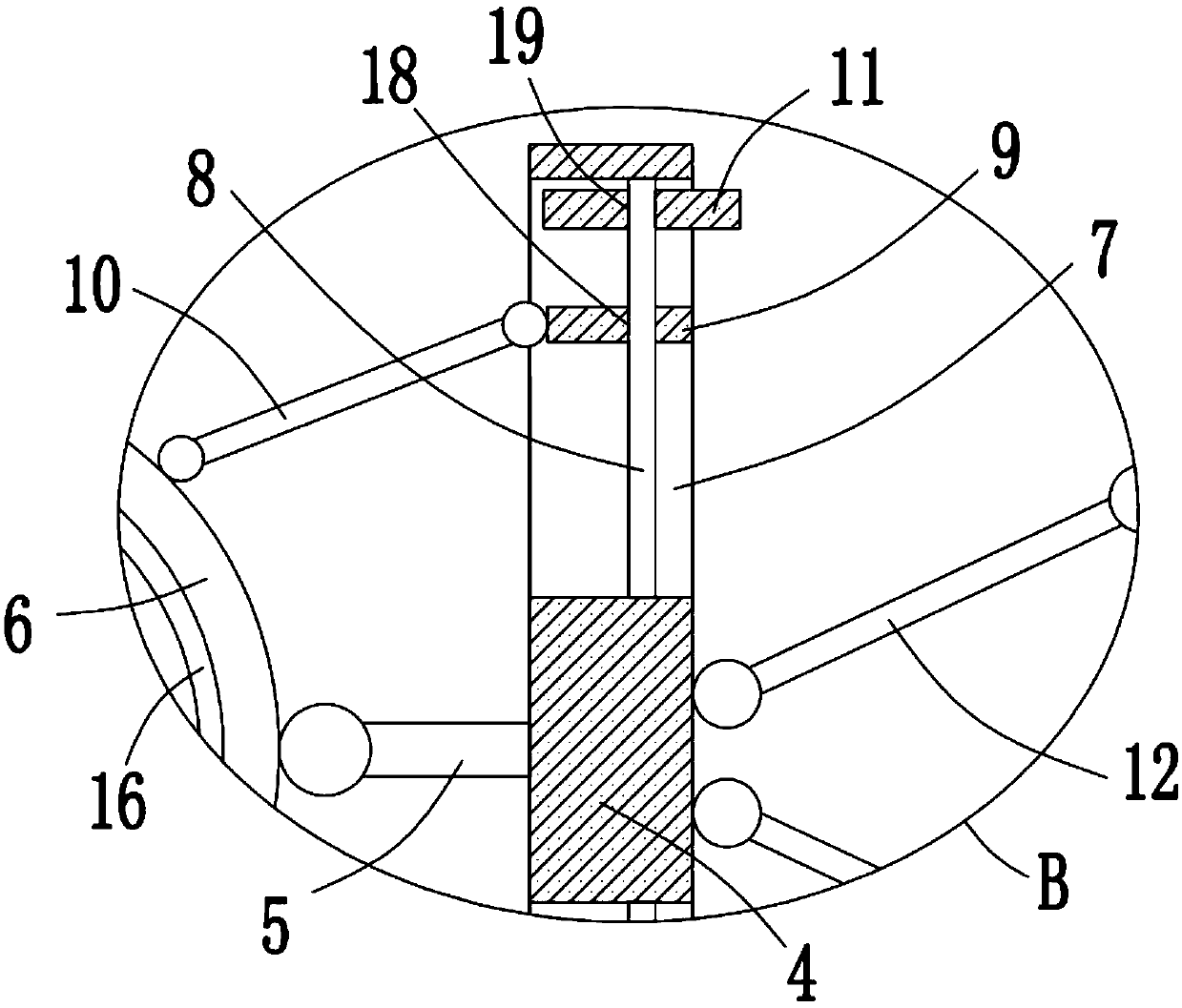
[0026] refer to Figure 1-5 In this embodiment, a fixture for processing cylindrical parts is proposed, including a base 1, a push rod motor 3 is fixedly installed on both sides of the top of the base 1, and a first plate 2 is fixedly installed on the output shaft of the push rod motor 3 , the two first plates 2 are located between the two push rod motors 3, two second plates 4 are arranged between the two first plates 2, and the sides of the two second plates 4 close to each other are fixedly installed with Rotating rod 5, one end of two rotating rods 5 close to each other is all rotated and installed with arc-shaped elastic splint 6, and the side of two second plates 4 close to each other is provided with two rectangular holes 7, the top inner wall of rectangular hole 7 and The same screw rod 8 is rotated on the inner wall of the bottom, and a slide plate 9 is threaded on the screw rod 8, and the slide plate 9 is slidably installed in the corresponding rectangular hole 7. Th...


PUM


Abstract

The invention discloses a fixture for conveniently machining cylindrical parts. The fixture includes a base; pushing rod motors are fixedly mounted on the two sides of the top of the base, first plates are fixedly mounted on the output shafts of the pushing rod motors, the two first plates are both located between the two pushing rod motors, and two second plates are arranged between the two firstplates; rotating rods are fixedly mounted on one sides, close to each other, of the two second plates, and arc elastic clamping plates are rotatbly mounted at the ends, close to each other, of the two rotating rods; and two rectangular holes are formed in the sides, close to each other, of the two second plates, a screw rod is rotatably mounted on the inner walls of the top and the bottom of eachrectangular hole, a sliding plate is mounted on each screw rod in a threaded mode, and the sliding plates are slidably mounted in the corresponding rectangular holes. The fixture is reasonable in design, high in practicability and simple in structure, the bending degree of the arc elastic clamping plates is adjusted conveniently according to the diameter size of the cylindrical parts, the cylindrical parts are convenient to clamp, and using of the workers is facilitated.

Description

technical field [0001] The invention relates to the technical field of processing fixtures, in particular to a fixture for processing cylindrical parts. Background technique [0002] Clamping devices are widely used in manufacturing industries, such as stamping, riveting, welding, pasting or solidification of workpieces, etc. During the above-mentioned processing processes, it is often necessary to maintain the correct positional relationship of parts. Clamping devices have various reference surfaces or points, so that Workpieces can be positioned precisely, so clamping devices are considered essential components in the machining industry. [0003] At present, when processing cylindrical parts, workers generally fix the position of cylindrical parts manually, which is not convenient for stable clamping of cylindrical parts, and the positioning efficiency of cylindrical parts is low, which affects the use of workers. The jig is used to solve the above problems. Contents of...

Claims


Application Information

Patent Timeline
IPC IPC(8): B25B11/00
CPCB25B11/00
Inventor 黄海光罗丙球
Owner 柳州通亿汽车配件制造有限公司
Learn More