Lofting method of retractable fin stabilizer shell plate

A fin stabilizer, retractable technology, used in the use of hydrofoils to act on the surrounding water surface to reduce ship motion, ship construction, ship design, etc. and other problems to achieve the effect of improving work efficiency

Active Publication Date: 2018-10-19
CSSC HUANGPU WENCHONG SHIPBUILDING COMPANY
View PDF5 Cites 12 Cited by
  • Summary
  • Abstract
  • Description
  • Claims
  • Application Information

AI Technical Summary

Problems solved by technology

However, the structure of the fin stabilizer is relatively complicated, and the outer plate of the fin stabilizer is required to be sent to the manufacturer to be installed together with the fin stabilizer, whi

Method used


Image

  • Lofting method of retractable fin stabilizer shell plate
  • Lofting method of retractable fin stabilizer shell plate
  • Lofting method of retractable fin stabilizer shell plate

Examples


Embodiment Construction

[0023] The specific implementation manners of the present invention will be further described in detail below in conjunction with the accompanying drawings and embodiments. The following examples are used to illustrate the present invention, but are not intended to limit the scope of the present invention.

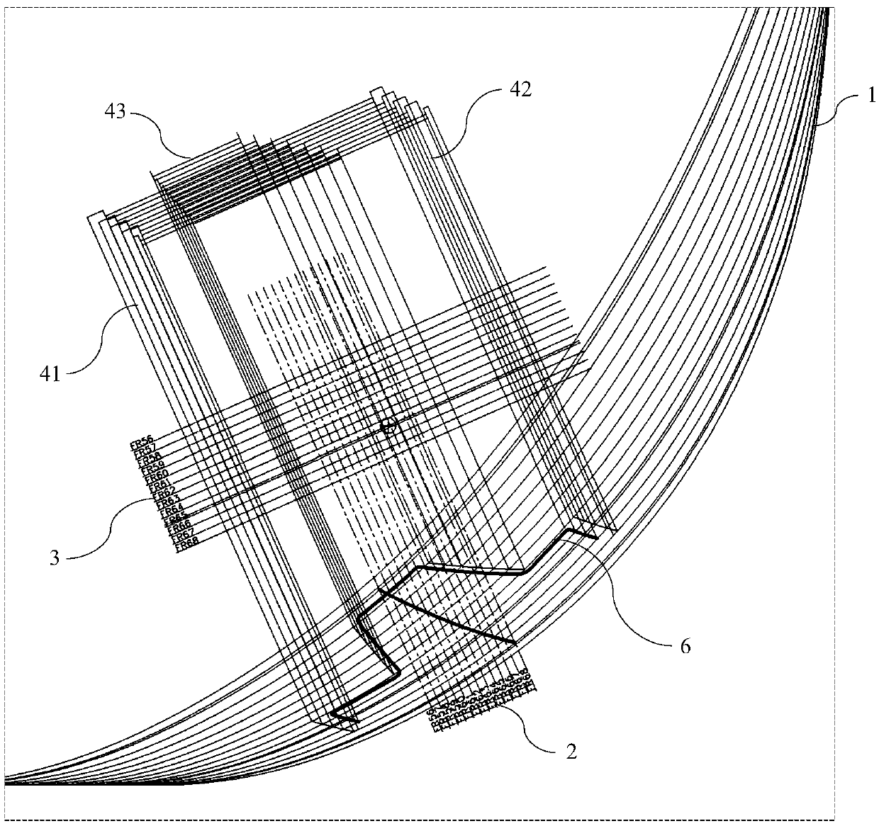
[0024] to combine Figures 1 to 4 As shown, schematically shows the lofting method of the retractable fin stabilizer outer plate of the present invention, including the following steps:

[0025] Step S1, combining figure 1 As shown, obtain the rib shape line diagram, which includes the rib line 1 of the hull, and mark the fin stabilizer centerline 2, fin box structure contour line 4 and fin box centerline 3 on the rib shape line diagram, where , the fin box structure contour line 4 includes the fin box upper structure line 41, the fin box lower structure line 42 and the fin box roof line 43;

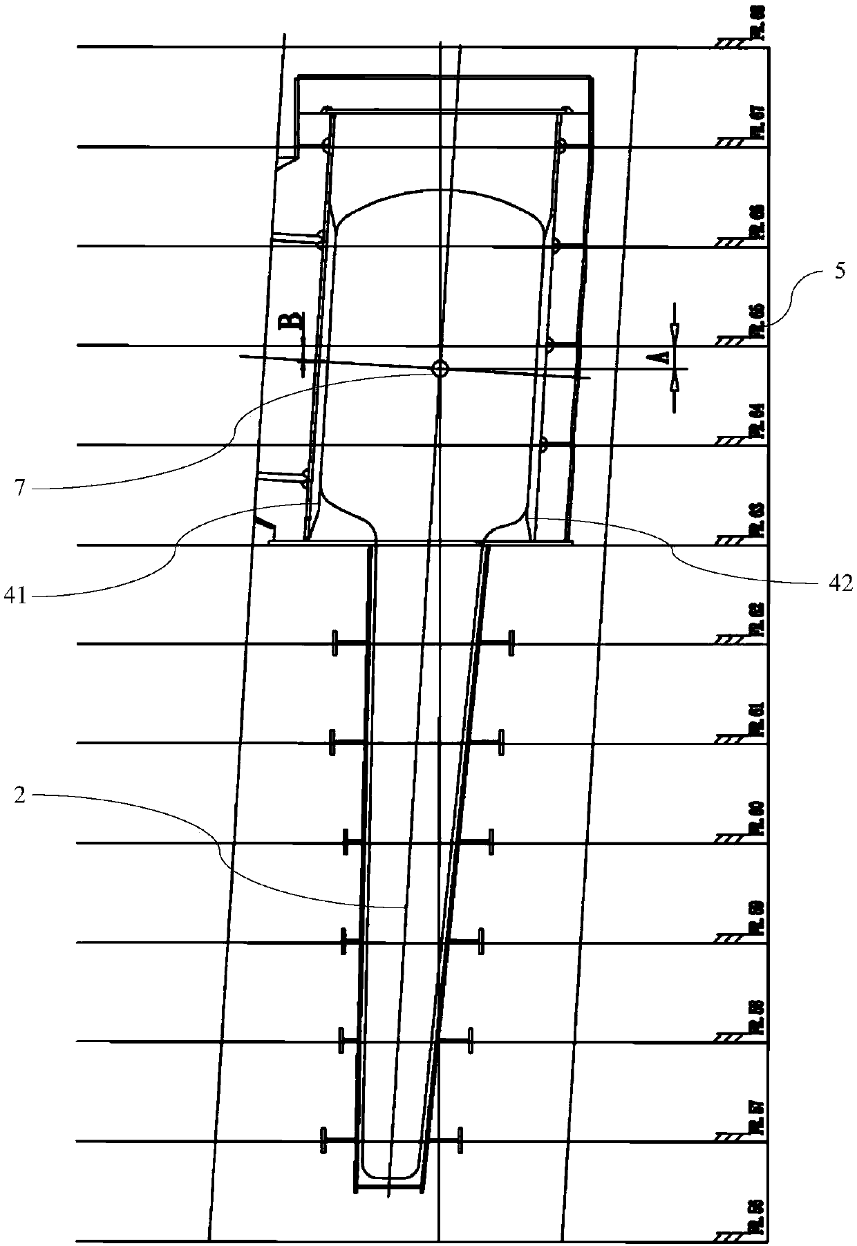
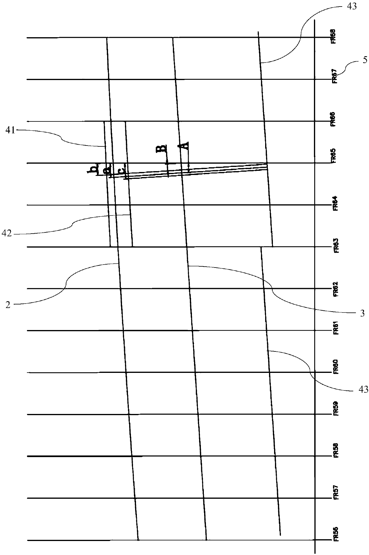
[0026] Step S2, such as figure 2 As shown, obtain the projection diagram of...


PUM


Abstract

The invention relates to the field of shipbuilding, in particular to a lofting method of a retractable fin stabilizer shell plate. The lofting method of the retractable fin stabilizer shell plate comprises the steps of labeling a fin stabilizer center line, a fin box center line, a fin box upper structural line, a fin box lower structural line and a fin box roof line on a frame body plan; after obtaining a fin box opening projection drawing, drawing a fin box opening plane development according to the fin box opening projection drawing; and labeling the true shape of a cross head rotating transverse center line on a fin box shell plate expansion plan according to the fin box opening projection drawing and the fin box opening plane development. According to the lofting method of the retractable fin stabilizer shell plate, a fin box shell plate is simply, conveniently and rapidly unfolded; and the cross head rotating center line, the fin stabilizer center line and so on are labeled on the fin box shell plate expansion plan; and therefore, the working efficiency is enhanced.

Description

technical field [0001] The invention relates to the field of shipbuilding, in particular to a lofting method for a retractable fin stabilizer outer plate. Background technique [0002] The fin stabilizer is currently the most effective anti-rolling device. It is installed in the bilge of the two sides of the ship, mainly to reduce the rolling effect of the hull and improve the safety of the ship. It is divided into two categories: non-retractable fin stabilizer and retractable fin stabilizer. The retractable fin stabilizer has a higher anti-roll effect, so it is widely used in various engineering ship types. However, the structure of the fin stabilizer is relatively complicated, and the outer plate of the fin stabilizer is required to be sent to the manufacturer to be installed together with the fin stabilizer, which requires high precision. The guidance of lofting process makes it very difficult for inexperienced staff to do lofting, and often makes mistakes, resulting in ...

Claims


Application Information

Patent Timeline
IPC IPC(8): B63B9/00G06F17/50
CPCB63B71/00B63B71/10G06F30/15B63B39/06
Inventor 黄红松杨秀峰蒋志跃邹晓峰饶宇中姜涛
Owner CSSC HUANGPU WENCHONG SHIPBUILDING COMPANY
Why Eureka
Try Eureka