Shell surface treatment method, shell and terminal equipment

A technology for surface treatment and terminal equipment, which is applied in branch office equipment, devices for coating liquid on the surface, ion implantation plating, etc., can solve the problem of inability to achieve seamless docking, leaving assembly gaps, affecting the visual effect of terminal equipment, etc. problems, to achieve the effect of enhancing market competitiveness, increasing integrity, and improving user experience

Active Publication Date: 2018-10-19
VIVO MOBILE COMM CO LTD
View PDF11 Cites 7 Cited by
  • Summary
  • Abstract
  • Description
  • Claims
  • Application Information

AI Technical Summary

Problems solved by technology

However, when raw materials of different materials are assembled on the terminal equipment, there is usually an assembly gap, which cannot be seamlessly connected, thus affecting the visual effect of the terminal equipment

Method used


Image

  • Shell surface treatment method, shell and terminal equipment
  • Shell surface treatment method, shell and terminal equipment
  • Shell surface treatment method, shell and terminal equipment

Examples


Embodiment Construction

[0016] The following will clearly and completely describe the technical solutions in the embodiments of the present invention with reference to the accompanying drawings in the embodiments of the present invention. Obviously, the described embodiments are part of the embodiments of the present invention, but not all of them. Based on the embodiments of the present invention, all other embodiments obtained by persons of ordinary skill in the art without creative efforts fall within the protection scope of the present invention.

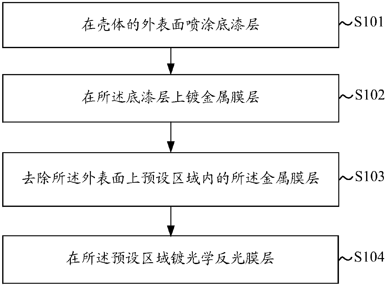
[0017] Such as figure 1 As shown, an embodiment of the present invention provides a surface treatment method for a shell, including the following steps:

[0018] S101: Spraying a primer layer on the outer surface of the casing.

[0019] The housing in this embodiment may be applied to terminal devices such as mobile phones, tablets, and personal computers, and specifically may be mobile phone housings; tablet housings; or computer housings and the lik...


PUM


Abstract

The embodiment of the invention discloses a shell surface treatment method, a shell and terminal equipment to realize seamless connection of the metal visual effect and the ceramic visual effect of the shell. The method comprises: spraying a primer layer on the outer surface of the shell; plating a metal film layer on the primer layer; removing the metal film layer from a preset area on the outersurface; and plating an optical reflective film layer in the preset area. The shell can be a same material and is formed integrally, from the perspective of outer surface of the shell, and the opticalreflective film layer in the preset area can present the visual effect of ceramic texture. The metal film layer outside the preset area can present the visual effect of metal texture, a metal and ceramic integrated visual effect can be realized on the shell, the integrity and sense of unity of the shell can be increased, and the shell looks like an integral whole visually.

Description

technical field [0001] The invention relates to the field of surface treatment, in particular to a method for surface treatment of a shell, the shell and terminal equipment. Background technique [0002] With the development of terminal equipment technology, users' requirements for the appearance of terminal equipment (such as mobile phones) are gradually showing a trend of diversification. At the same time, various terminal equipment with different visual effects appear on the market, which makes the appearance of terminal equipment more beautiful. exquisite. [0003] In order to reflect the difference in the appearance of the terminal equipment, the shell of the terminal equipment is sometimes a combination of several visual effects of different materials. The visual effect of the ceramic surface; as another example, the side of the terminal device has a visual effect of metallic luster, while the back of the terminal device has a visual effect similar to a smooth ceramic...

Claims


Application Information

Patent Timeline
IPC IPC(8): C23C14/20C23C14/58C23C14/08C23C14/04B05D7/02B05D7/14B05D7/24H04M1/02
CPCB05D7/02B05D7/14B05D7/24B05D2502/00C23C14/042C23C14/08C23C14/20C23C14/5873H04M1/0283
Inventor 张维吴晓楠罗逸余江林四亮
Owner VIVO MOBILE COMM CO LTD
Why Eureka
Try Eureka