
Intelligent uniform air supply device and method

An air supply device and uniform technology, which is applied in the field of intelligent uniform air supply device, can solve the problems of unstable outlet angle, unable to meet the conditions well, and unable to guarantee pressure loss at all times, so as to improve the air outlet uniformity, The effect of optimizing the air supply system and improving the comfort

Pending Publication Date: 2018-10-19
山东轨道交通勘察设计院有限公司 +1
View PDF0 Cites 7 Cited by
  • Summary
  • Abstract
  • Description
  • Claims
  • Application Information

AI Technical Summary

Problems solved by technology

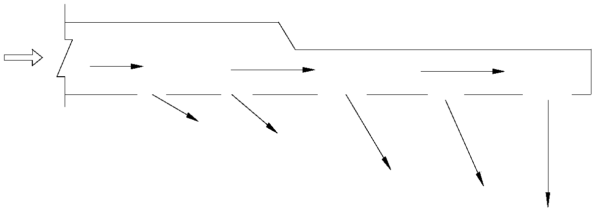
[0023] From the above analysis, it can be seen that the first method cannot always ensure that the dynamic pressure drop between the holes on both sides is equal to the pressure loss between the holes on both sides, and the outflow angle is also unstable, which cannot satisfy the conditions (1) and ( 3); No matter how good the designer is, in a fixed system, it cannot guarantee that the ratio of the air flow out of the orifice of a system to the air volume in front of the orifice remains unchanged, so the first method cannot satisfy the condition of uniform air supply (2)
[0024] Although the second method can satisfy the condition (3) of uniform air supply, it also cannot satisfy the conditions (1) and (2) very well.
Therefore, although method 2 is an improvement over method 1, it still cannot completely solve the problem of uniform air supply.

Method used


Image

  • Intelligent uniform air supply device and method
  • Intelligent uniform air supply device and method
  • Intelligent uniform air supply device and method

Examples


Embodiment Construction

[0057] The present invention will be further described below in conjunction with the accompanying drawings and embodiments.

[0058] It should be pointed out that the following detailed description is exemplary and intended to provide further explanation to the present application. Unless defined otherwise, all technical and scientific terms used herein have the same meaning as commonly understood by one of ordinary skill in the art to which this application belongs.

[0059] It should be noted that the terminology used here is only for describing specific implementations, and is not intended to limit the exemplary implementations according to the present application. As used herein, unless the context clearly dictates otherwise, the singular is intended to include the plural, and it should also be understood that when the terms "comprising" and / or "comprising" are used in this specification, they mean There are features, steps, operations, means, components and / or combinatio...


PUM


Abstract

The invention discloses an intelligent uniform air supply device and method. The intelligent uniform air supply device comprises an air supply pipeline and adjustable air stop devices arranged in theair supply pipeline. The air supply pipeline is provided with a plurality of air outlets, and the adjustable air stop devices are arranged at the air outlets and are adjustable in angle. At least oneof the air outlets is provided with an anemometer, and the anemometer and the adjustable air stop devices are connected with a controller. The controller controls the angles of the adjustable air stopdevices according to the collected air speed and the air speed set value so that uniform air supply can be achieved.

Description

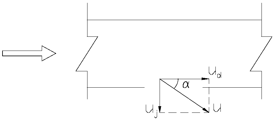
technical field [0001] The invention relates to an intelligent uniform air supply device and method. Background technique [0002] At present, there are two commonly used air supply methods in large underground station systems in the subway industry. figure 1 And attached figure 2 . attached figure 1 The air outlet is directly installed on the air supply main pipe, and the attached figure 2 The air outlet is installed at the short pipe port. [0003] See attached image 3 , when the air flows in the duct, its static pressure acts vertically on the duct wall. If a hole is made on the side wall of the air duct, due to the static pressure difference inside and outside the orifice, the air will flow out from the orifice in a direction perpendicular to the pipe wall. The flow rate due to the static pressure difference is: [0004] [0005] The velocity of air in the duct is: [0006] [0007] In the formula: [0008] p j is the static pressure of the air in the...

Claims


Application Information

Patent Timeline
IPC IPC(8): F24F13/06F24F13/14F24F11/74F24F11/79
CPCF24F11/74F24F11/79F24F13/06F24F13/1413F24F2013/0608Y02B30/70
Inventor 李虎张双燕时磊殷芳吴乃亮吕晓辉巩朦孙杰彭晓娟种纪森
Owner 山东轨道交通勘察设计院有限公司
Learn More