
Load switch control circuit

A technology for controlling circuits and load switches, which is applied to circuits, electronic switches, electrical components, etc., and can solve problems such as excessive voltage rise at the load end

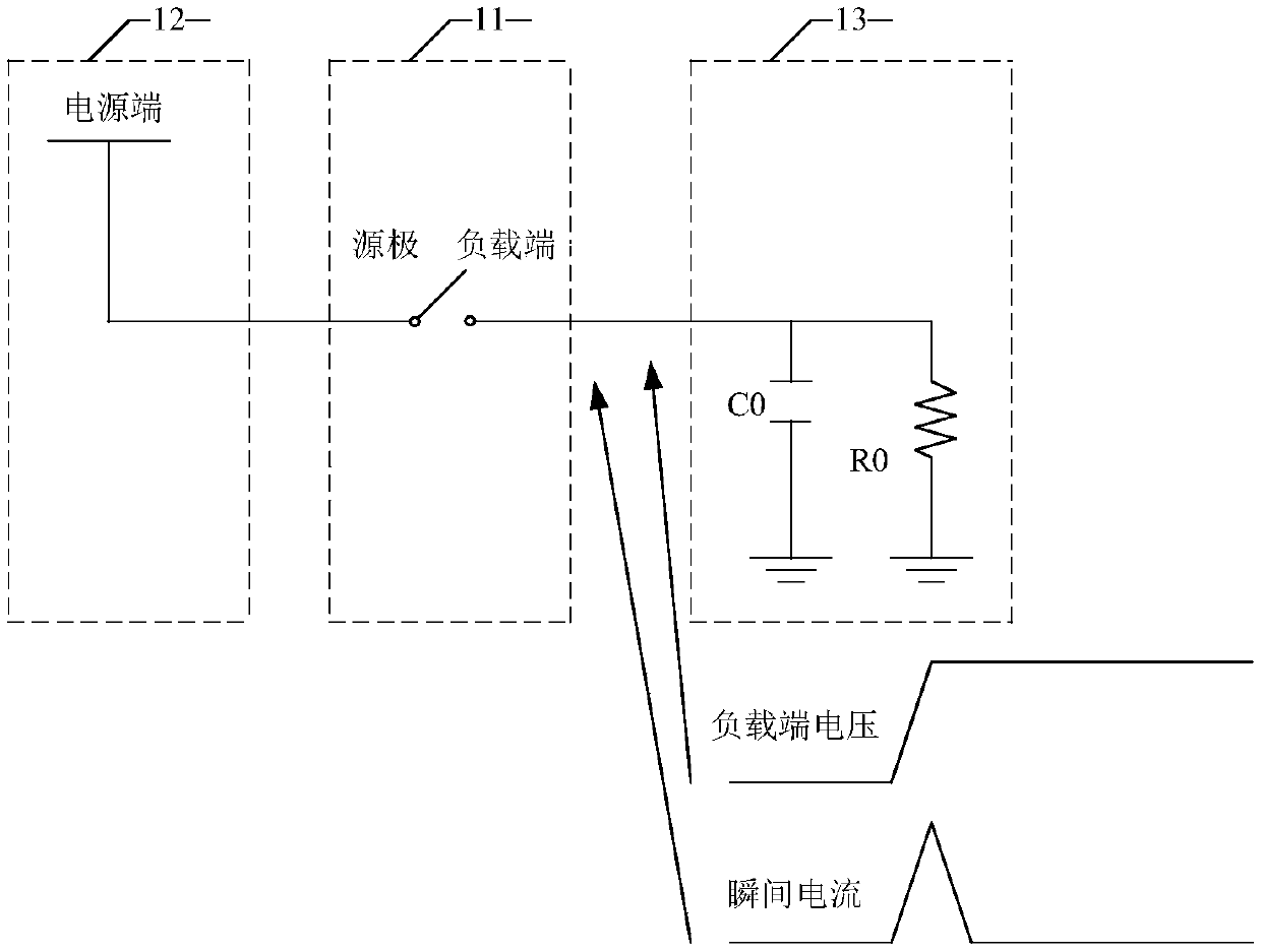
Active Publication Date: 2018-10-19
SHANGHAI AWINIC TECH CO LTD
View PDF18 Cites 2 Cited by
  • Summary
  • Abstract
  • Description
  • Claims
  • Application Information

AI Technical Summary

Problems solved by technology

[0006] However, the stage where the on-resistance of the load switch changes the fastest is the stage after the gate-source voltage exceeds the threshold, and this stage happens to be the stage where the gate-source voltage changes the fastest generated by the traditional control method, so through the existing technology The control method still causes the voltage at the load terminal to rise too fast

Method used


Image

  • Load switch control circuit
  • Load switch control circuit
  • Load switch control circuit

Examples


Embodiment Construction

[0041] The following will clearly and completely describe the technical solutions in the embodiments of the present invention with reference to the accompanying drawings in the embodiments of the present invention. Obviously, the described embodiments are only some, not all, embodiments of the present invention. Based on the embodiments of the present invention, all other embodiments obtained by persons of ordinary skill in the art without making creative efforts belong to the protection scope of the present invention.

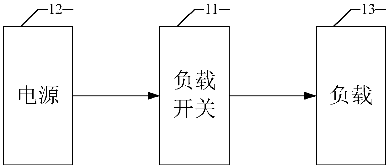
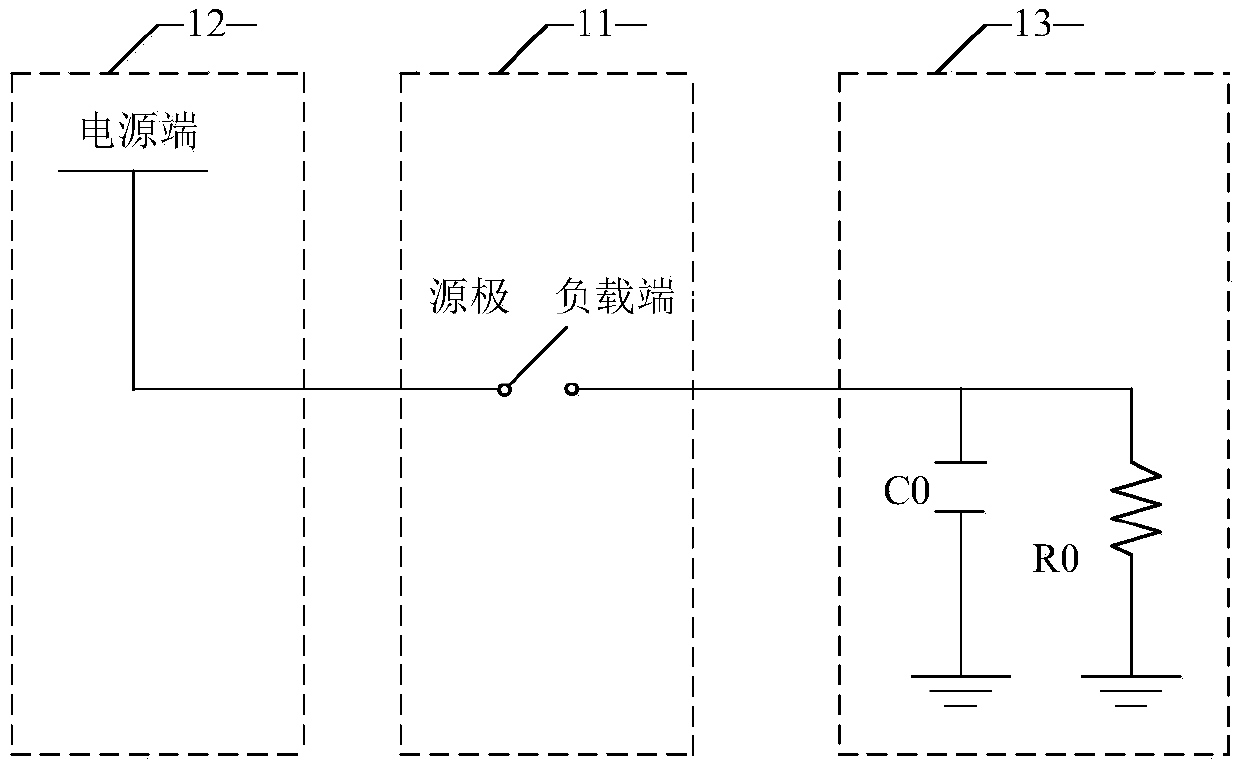
[0042] like figure 1 As shown, the load switch 11 is mainly used to connect the power supply 12 and the load 13 to realize the connection and isolation between the two, as figure 2 As shown, the source of the load switch 11 is connected to the power supply terminal, and the load terminal of the load switch 11 is connected to the load 13, wherein the load 13 is illustrated by a capacitor C0 and a resistor R0. It should be noted that the load 13 can also be con...


PUM


Abstract

The invention discloses a load switch control circuit. The load switch control circuit comprises a voltage generating module, a main switch tube, a voltage rising rate acquisition module and a feedback control module, wherein the voltage generating module is used for generating starting voltage required for starting a main switch; the voltage rising rate acquisition module is used for acquiring the rising rate of output voltage of the main switch; and the feedback control module is used for controlling the starting voltage according to the rising rate, so that the rising rate is controlled. The load switch control circuit can be used for directly controlling the rising rate of the load voltage in a load switch starting process fundamentally; the surge current phenomenon is eliminated greatly; and the system stability is improved.

Description

technical field [0001] The present invention relates to the technical field of semiconductor integrated circuits, and more specifically, relates to a load switch control circuit. Background technique [0002] A load switch is a commonly used device in electronic systems, used to connect a power supply and a load to realize connection and isolation between the two, such as power-on and power-off. Wherein, the load switch can be integrated with its control circuit, or it can be a discrete component. [0003] Field effect transistor is a commonly used load switch. However, when the existing field effect transistor is used as a load switch, it often transmits a relatively large surge current into the load connected to it, causing certain damage to the load. Among them, Inrush current is a phenomenon that a large current is introduced into the load end due to the fast turn-on speed of the load switch at the moment of turn-on. [0004] In order to avoid the inrush current phenom...

Claims


Application Information

Patent Timeline
Patent Type & Authority Applications(China)
IPC IPC(8): H03K17/687H03K17/082
CPCH03K17/0822H03K17/687H03K2217/0054H03K2217/0081
Inventor 何永强程剑涛郭辉张艳萍
Owner SHANGHAI AWINIC TECH CO LTD
Learn More