
Optical lens back focus adjusting device

A technology of optical lens and adjustment device, which is applied in TV, color TV parts, electrical components, etc. It can solve the problems of blurred image, affecting imaging effect, unclear focus, etc., and achieve the effect of accurate focus

Pending Publication Date: 2018-10-19
UNION OPTECH
View PDF0 Cites 0 Cited by
  • Summary
  • Abstract
  • Description
  • Claims
  • Application Information

AI Technical Summary

Problems solved by technology

The mechanical back focus refers to the distance between the mechanical rear end surface of the lens and the image plane. Whether it is a zoom lens or a fixed focus lens, when it corresponds to a chip, the value of the mechanical back focus is fixed. After the IR filter is removed from the structure, the image of the lens will become blurred, resulting in unclear focus and affecting the imaging effect
At the same time, when the general camera leaves the factory, the back focus is properly adjusted. Therefore, in the application where the customer is equipped with a fixed-focus or zoom lens, it is generally not necessary to adjust the back focus of the camera, but it may occur in normal use. When the lens focus ring is adjusted to the extreme position or the lens is subjected to relatively strong vibration, it can not get a clear image, then it is necessary to adjust the back focus
At the same time, the number of pixels of the network camera is getting larger and larger, but its high pixel number brings a clearer visual experience to the monitoring and also brings great difficulty to the engineering construction.
The traditional fixed back focus network camera can no longer meet the needs of high-definition monitoring

Method used


Image

  • Optical lens back focus adjusting device
  • Optical lens back focus adjusting device
  • Optical lens back focus adjusting device

Examples


Embodiment Construction

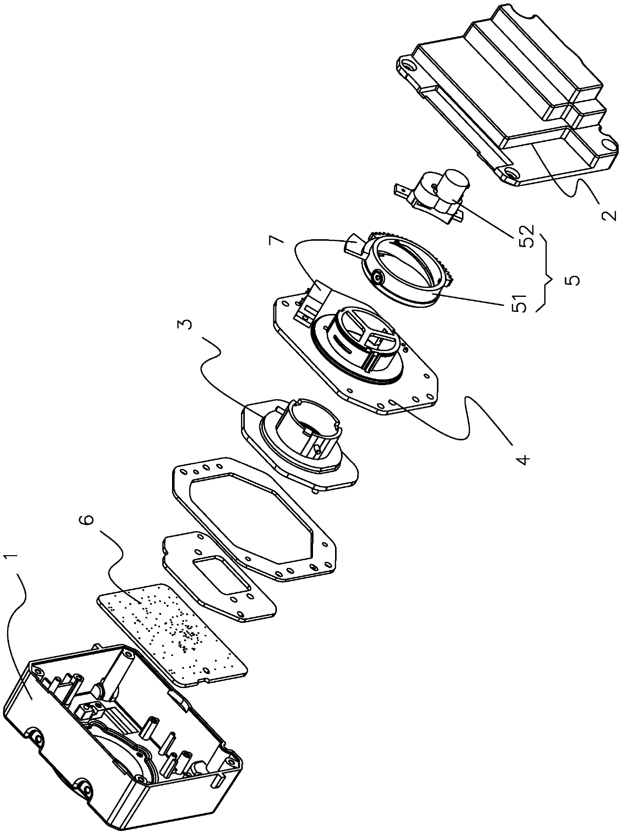
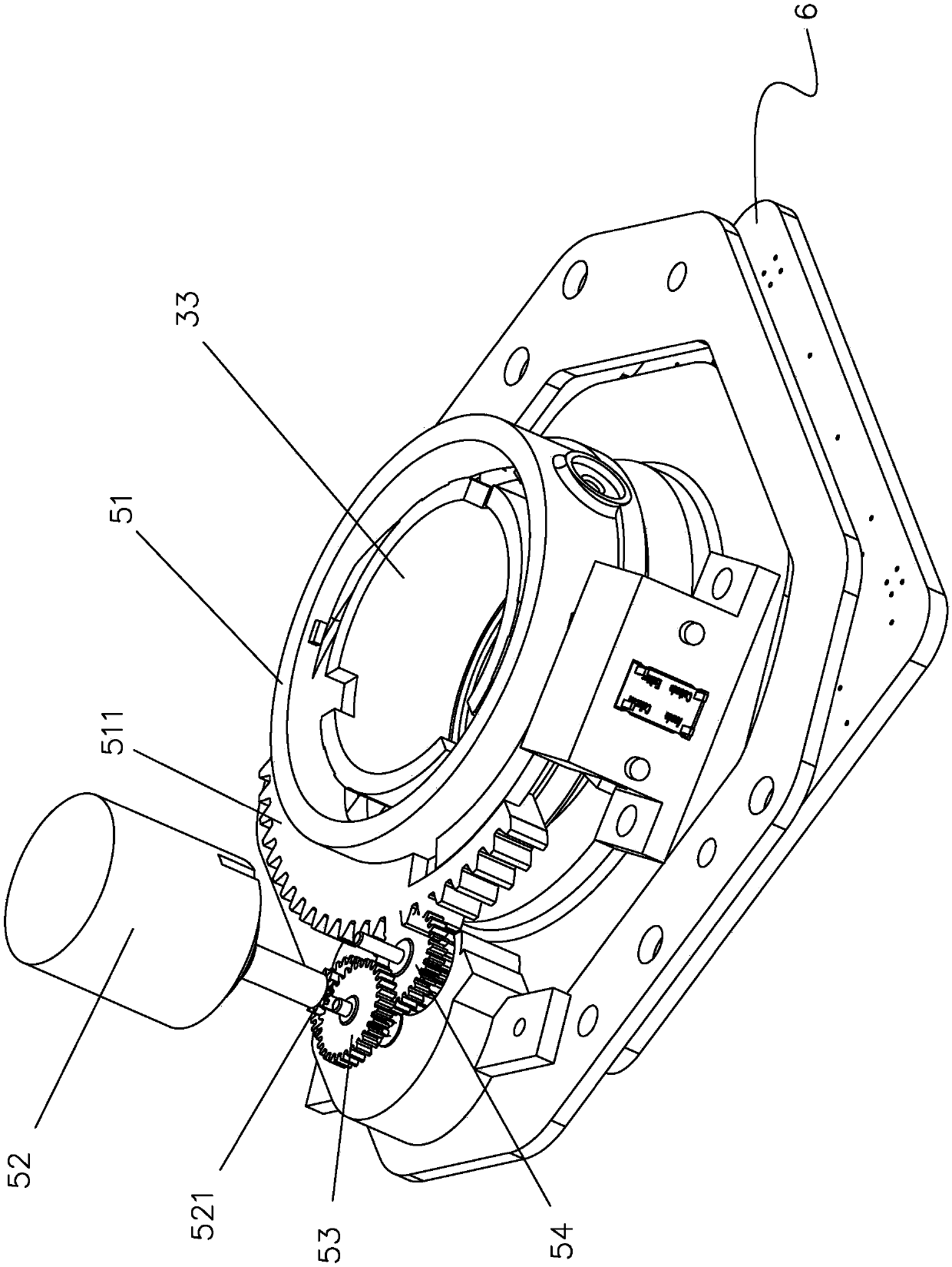
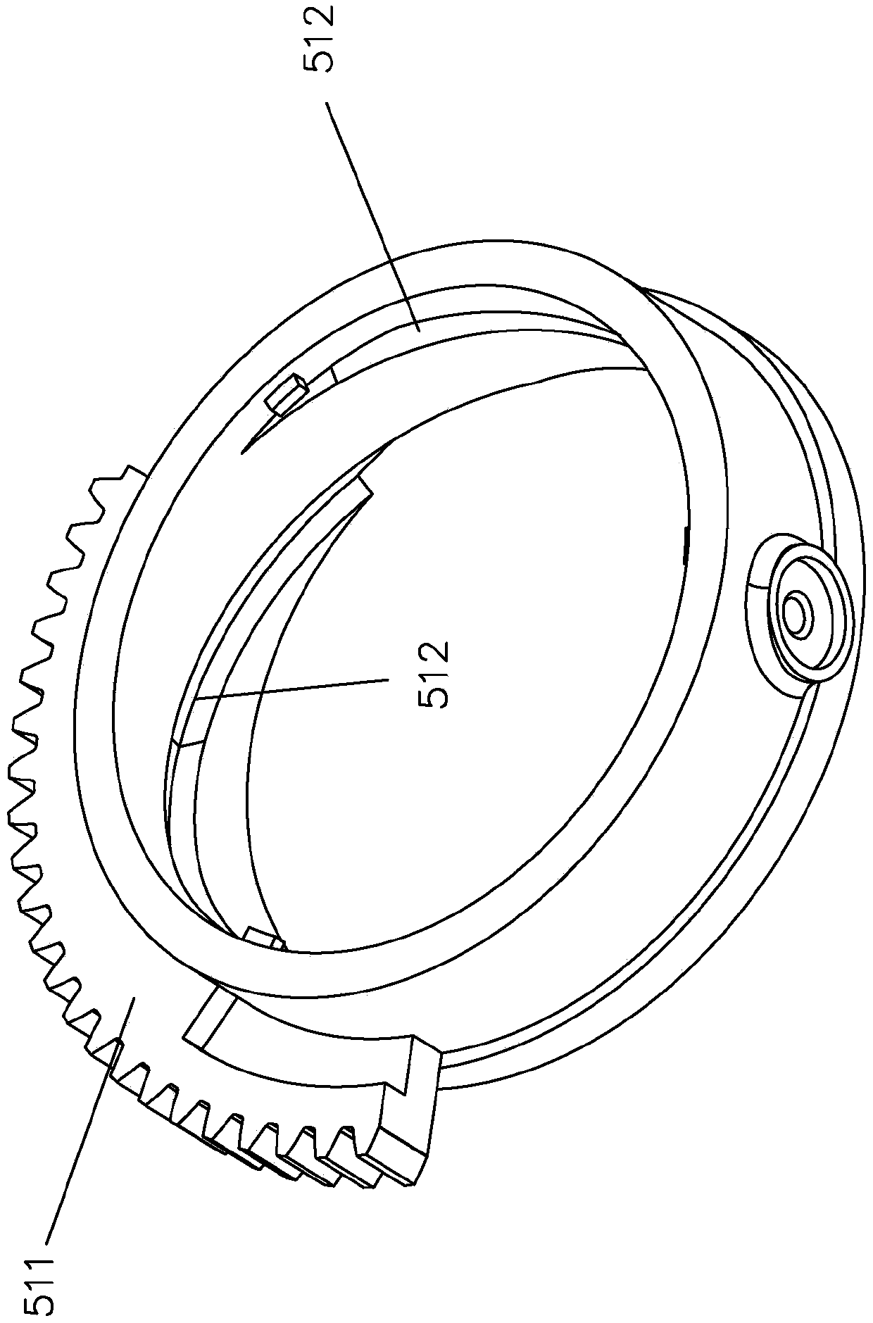
[0023] A kind of optical lens back focus adjustment device, comprises front cover 1, back cover 2 and is arranged in sequence from front to back between front cover 1 and back cover 2 moving part 3, guide cylinder 4 and driving device 5, front cover 1 The front portion is provided with a light-through hole 10, and the circumferential edge of the light-through hole 10 is provided with a mounting ring 11 that is socketed with the rear end of the optical lens, and the front end of the moving part 3 is provided with a CCD chip module 6 and the moving part 3 can The relative guide cylinder 4 moves forward and backward, and the driving device 5 includes a rotating sleeve 51 and a DC motor 52. The rotating sleeve 51 is sleeved on the guide cylinder 4 and is used to drive the rotating sleeve 51 of the moving part 3 to move back and forth. The output end of the DC motor 52 is provided with There is a gear 521 , and a rack 511 is provided on the circumferential outer side of the rotating...


PUM


Abstract

The invention provides an optical lens back focus adjusting device, comprising a front cover, a rear cover, and a moving part, a guiding cylinder and a driving device that are sequentially arranged between the front cover and the rear cover from front to back, wherein a light transmitting hole is formed in the front part of the front cover, a mounting ring for sleeving with the rear end of the optical lens is arranged on the circumferential edge of the light transmitting hole, a CCD chip module is arranged at the front end of the moving part, the moving part can perform back and forth movementrelative to the guiding cylinder, the driving device comprises a rotating sleeve and a DC motor, the rotating sleeve is sleeved on the guiding cylinder and is used for driving the moving part to moveback and forth, the output end of the DC motor is provided with a gear, the circumferential outer side of the rotating sleeve is provided with a rack, and a transmission gear component is meshed between the gear and the rack. The back focus adjusting device is sleeved on the rear end of the optical lens through the mounting ring, and the rear focal length is the distance between the rear end surface of the lens and an imaging surface formed by the CCD chip module, the driving device drives the moving part to move back and forth and further drives the imaging surface to move back and forth, and thus the adjustment of the back focus can be achieved.

Description

【Technical field】 [0001] The invention relates to the field of security optical lenses, in particular to an optical lens rear focus adjustment device. 【Background technique】 [0002] With the rapid development of high technology, security optical zoom and fixed focus lenses have been widely used. The mechanical back focus refers to the distance between the mechanical rear end surface of the lens and the image plane. Whether it is a zoom lens or a fixed focus lens, when it corresponds to a chip, the value of the mechanical back focus is fixed. After the IR filter is removed from the structure, the image of the lens will become blurred, resulting in unclear focus and affecting the imaging effect. At the same time, when the general camera leaves the factory, the back focus is properly adjusted. Therefore, in the application where the customer is equipped with a fixed-focus or zoom lens, it is generally not necessary to adjust the back focus of the camera, but it may occur in n...

Claims


Application Information

Patent Timeline
IPC IPC(8): H04N5/225
CPCH04N23/50H04N23/55H04N23/54
Inventor 赵媚娇邱盛平李中杰李昆冯建昭谭穗静吴恙王琦吴景忠宋利华谢燕均陈安科郑文龙
Owner UNION OPTECH
Learn More