distance measuring device

A technology of distance measuring device and main body, which is applied in the direction of measuring device, radio wave measuring system, electromagnetic wave re-radiation, etc. It can solve the problem that it is difficult to adjust to the focus position accurately, achieve good operation convenience, precise focus, and reduce cost and waste Effect

Active Publication Date: 2011-12-07
ASIA OPTICAL CO INC
View PDF4 Cites 4 Cited by
  • Summary
  • Abstract
  • Description
  • Claims
  • Application Information

AI Technical Summary

Problems solved by technology

[0005] The technical problem to be solved by the present invention is to provide a distance measuring device that can easily adjust the receiving component to an appropriate focus and foc

Method used


Image

  • distance measuring device
  • distance measuring device
  • distance measuring device

Examples


Embodiment Construction

[0015] The preferred embodiments of the present invention are described hereby in conjunction with the accompanying drawings.

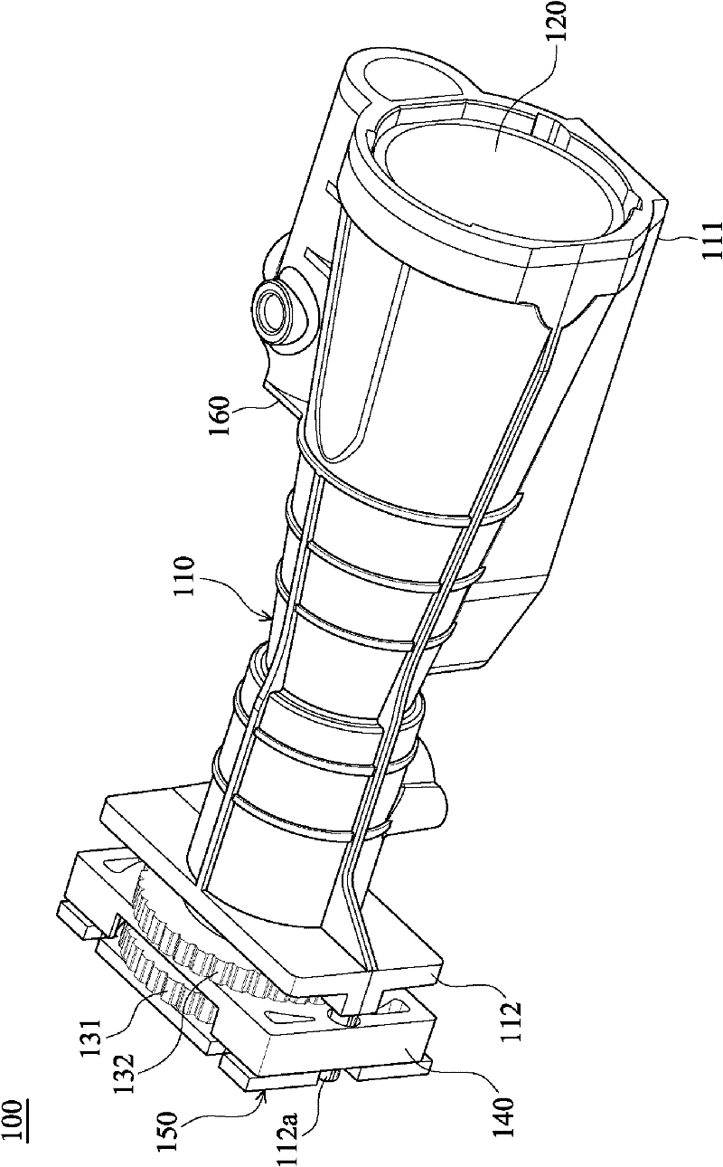
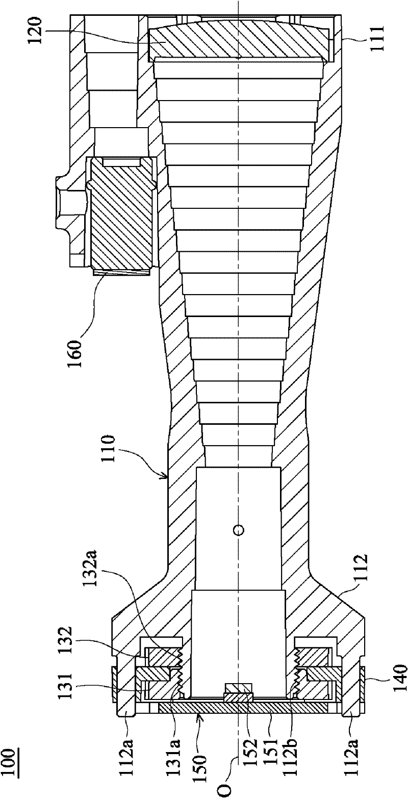
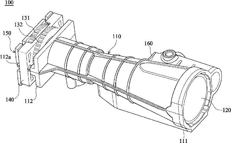
[0016] see figure 1 and figure 2 The distance measuring device 100 of this embodiment mainly includes a main body 110 , a receiving lens 120 , a first locking wheel 131 , a second locking wheel 132 , a moving plate 140 , a receiving component 150 and an emitting light source 160 .

[0017] The body 110 has a first end 111 and a second end 112 . The first end 111 is opposite to the second end 112 . In addition, if figure 2 As shown, the second end 112 has two opposite guide rods 112a and a third threaded portion 112b.

[0018] Such as figure 1 and figure 2 As shown, the receiver lens 120 is connected to the first end 111 of the body 110 .

[0019] Both the first locking wheel 131 and the second locking wheel 132 are connected to the second end 111 of the main body 110 in a rotational manner. In more detail, as figure 2 As shown, the first ...


PUM


Abstract

The invention relates to a ranging device, which comprises a body, a receiving lens, a first locking wheel, a second locking wheel, a movable plate and a receiving component, wherein the body is provided with a first end and a second end; the first end is opposite to the second end, and the second end is provided with at least one guide rod; the receiving lens is connected to the first end of the body; the first locking wheel and the second locking wheel are connected to the second end of the body in a rotary mode; the movable plate is sleeved on the guide rod of the second end of the body in a movable mode and is arranged between the first locking wheel and the second locking wheel; and the receiving component is connected to the movable plate and is used for receiving light beams received by the receiving lens. The movable plate moves through the rotation of the first locking wheel and the second locking wheel so as to drive the receiving component to move on an optical axis.

Description

technical field [0001] The present invention relates to a distance-measuring device, in particular to a distance-measuring device capable of easily adjusting the receiving component to a proper focus and optical axis position. Background technique [0002] In general, there are various forms of distance measuring devices currently on the market. For example, a laser ruler is a distance measuring device. [0003] The laser ruler mainly includes a laser light source, a transmitting lens, a receiving lens and a receiving component. When the laser ruler is used for distance measurement, the laser light source will emit a 650nm red laser, and the red laser will be collimated by the emitting lens into an approximately parallel laser beam. Then, when the laser beam strikes a target object, diffuse reflection will occur, and the receiving lens can receive the reflected laser beam and focus it on the receiving component. Then, the laser beam received by the receiving component can...

Claims


Application Information

Patent Timeline
IPC IPC(8): G01S17/08
Inventor 黄鑫弘刘华唐
Owner ASIA OPTICAL CO INC
Why Eureka
Try Eureka