Supercharge Your Innovation With Domain-Expert AI Agents!

Especially for actuating devices of friction clutches

A technology of manipulating devices and friction devices, applied in the direction of friction clutches, clutches, fluid-driven clutches, etc.

Active Publication Date: 2021-05-14
ZF FRIEDRICHSHAFEN AG
View PDF7 Cites 0 Cited by
  • Summary
  • Abstract
  • Description
  • Claims
  • Application Information

AI Technical Summary

Problems solved by technology

A fundamental disadvantage of this design principle is that the wear compensation chamber must be permanently under operating pressure, since the displacement working chamber is functionally supported on the wear compensation chamber

Method used


Image

  • Especially for actuating devices of friction clutches
  • Especially for actuating devices of friction clutches
  • Especially for actuating devices of friction clutches

Examples


Embodiment Construction

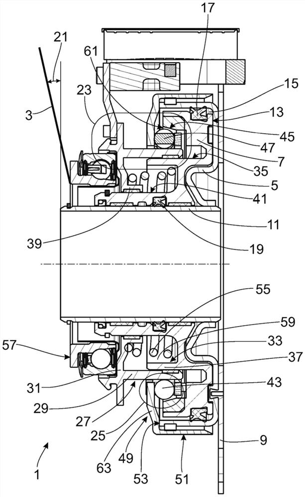
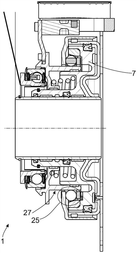
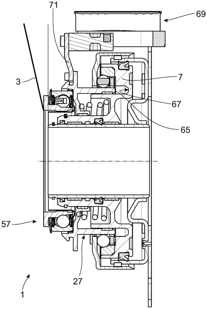
[0045] figure 1 The illustration is limited to an actuating device 1 for a friction clutch in a drive train. The specific structure of the friction clutch is not critical to the invention. For a friction clutch, an actuating lever 3 is shown symbolically, such as a reed like a diaphragm spring known per se.

[0046]The actuating device 1 comprises a working cylinder 5 in which a piston 7 is guided axially displaceably. The working cylinder 5 is secured in a positionally defined manner inside a clutch bell (not shown) via a preferably riveted support plate 9 . A bearing sleeve 11 on which the piston 7 slides is fastened coaxially with respect to the working cylinder 5 . The working cylinder 5 , the rear surface 13 of the piston 7 and the bearing sleeve 11 delimit a working chamber 15 which can optionally be filled with a gaseous or hydraulic pressure medium. Seals 17 , 19 prevent pressure medium from escaping at the inner and outer side surfaces of piston 7 . For the sake ...


PUM


Abstract

The invention relates to an actuating device comprising a working cylinder that can be filled with a pressure medium, in which a piston is displaceably guided, wherein a compensating device acts in series with the working cylinder, the compensating device The working range of the piston is shifted over its effective axial length, wherein the compensating device has a mechanical locking device for fixing its effective length.

Description

technical field [0001] The invention relates to an actuating device for a friction clutch. The actuating device comprises a working cylinder which can be filled with a pressure medium, in which the piston is displaceably guided, wherein a compensating device acts in series with the working cylinder, by means of which the compensating device effectively The axial length moves the piston to the working area. Background technique [0002] Document DE 102 53 020 A1 describes an actuating device for a friction clutch. Compressed air is used as the pressure medium for the actuation device. In addition to numerous advantages, however, compressibility must be considered for compressed air. In contrast to hydraulic pressure media, a delay occurs when activating the actuating device. Furthermore, attempts are made to optimize this delay by minimizing the volume of the working chamber. This results in a partially complex body contour in the cylinder of the piston displaceably moun...

Claims


Application Information

Patent Timeline
Patent Type & Authority Patents(China)
IPC IPC(8): F16D13/75F16D13/58F16D25/08
CPCF16D13/58F16D13/752F16D25/083F16D13/755F16D25/087F16D25/126F16D2300/18
Inventor F·厄布M·戴默M·多伊尔弗勒C·施莱彻B·图拉兹科H·沃伊特H·伯文德B·科埃斯特S·格拉西门科
Owner ZF FRIEDRICHSHAFEN AG
Features
  • R&D
  • Intellectual Property
  • Life Sciences
  • Materials
  • Tech Scout
  • Unparalleled Data Quality
  • Higher Quality Content
  • 60% Fewer Hallucinations
Learn More