Friction element for transmission

A friction element and transmission technology, applied in the field of friction elements, can solve problems such as insufficient improvement of shifting feeling, and achieve the effect of improving shifting feeling.

Inactive Publication Date: 2018-10-23
HYUNDAI MOTOR CO LTD +1
View PDF0 Cites 0 Cited by
  • Summary
  • Abstract
  • Description
  • Claims
  • Application Information

AI Technical Summary

Problems solved by technology

Therefore, the buffer spring is not enough to improve the shift feel

Method used


Image

  • Friction element for transmission
  • Friction element for transmission
  • Friction element for transmission

Examples


Embodiment Construction

[0024] The following description is merely exemplary in nature, and is not intended to limit the present invention, application, or use. It should be understood that throughout the specification and drawings, corresponding reference numerals indicate the same or corresponding parts and features.

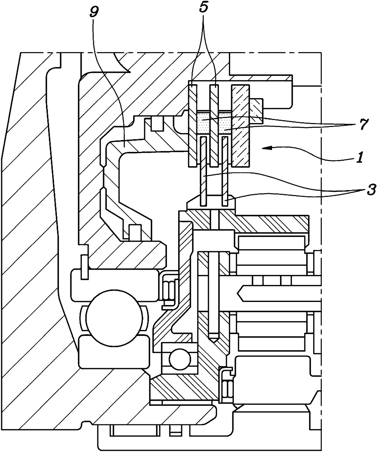
[0025] In one form of the present invention, a friction element for a transmission may include a multi-disc disc pack 1 and a continuous fastening device.

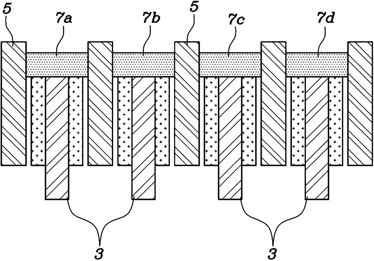
[0026] See figure 1 with figure 2 First, the multi-disc group 1 is formed to change the friction between the plurality of discs 3 and the plurality of discs 5 based on the operation of the piston 9. For example, the multi-disc group 1 may be a clutch or a brake provided as a friction element in an automatic transmission.

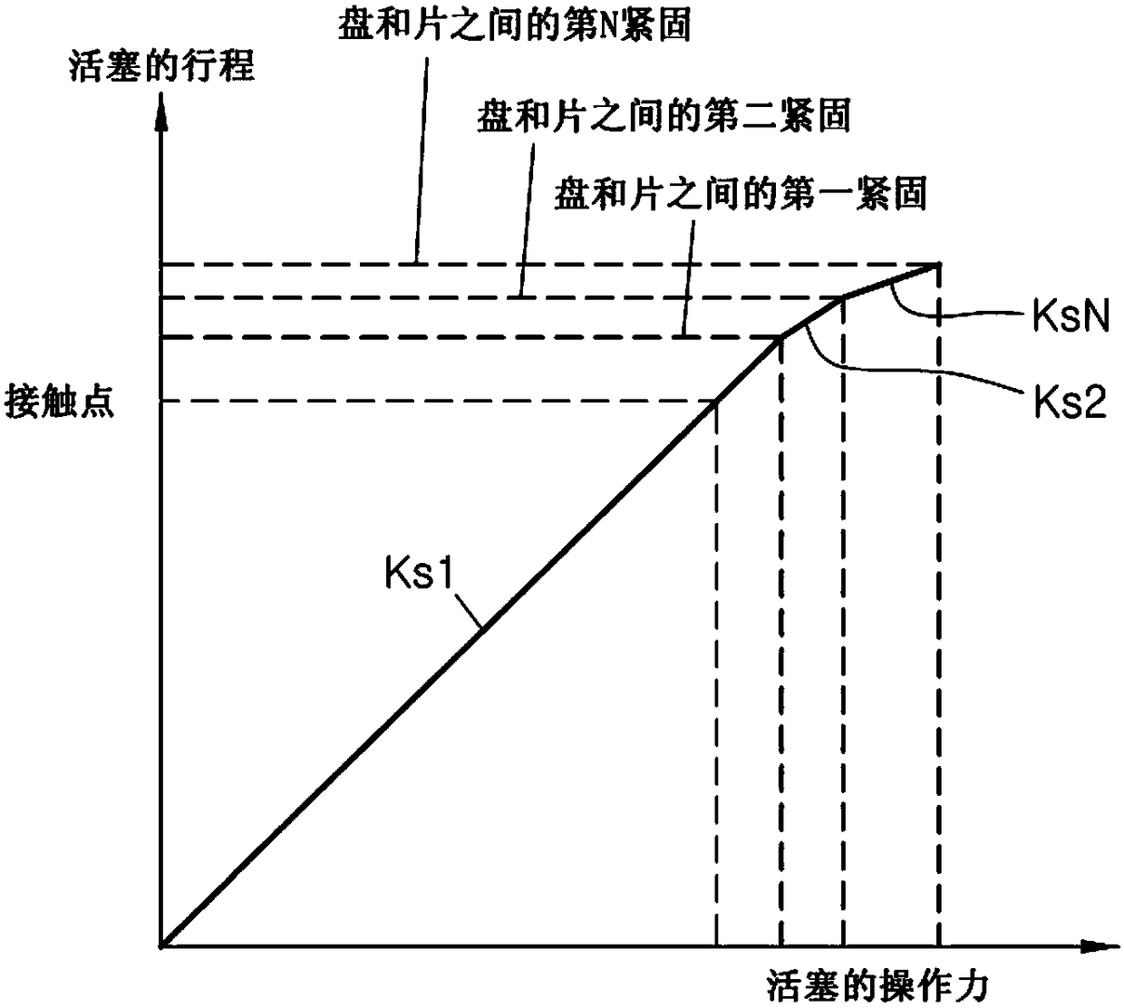
[0027] The continuous fastening device of the present invention may be configured to sequentially fasten the disc 3 and the sheet 5 according to the operation of the piston 9.

[0028] In one form, the continuous fas...


PUM


Abstract

The invention discloses a friction element for transmission, and relates to a technology which effectively absorbs a gear shifting impact by sequential fastening discs or plates to one another by a friction element. The friction element includes: a multi-plate disc set having discs and/or plates, and a fastening device having springs. In particular, the springs may start to be compressed from a spring having the smallest spring constant to a spring having a greater spring constant so as to sequentially fasten the discs and plates to one another so that the amount of a change in a stroke of a piston with respect to a change in an operation force of the piston is sequentially reduced.

Description

Technical field [0001] The invention relates to a friction element for a transmission. Background technique [0002] The statements in this section only provide background information related to the present invention and do not constitute prior art. [0003] In a vehicle equipped with an automatic transmission, the torque converter transmits the rotational power generated by the engine to the transmission, and the transmission transmits the rotational power of the engine to the drive shaft via an appropriate gear. [0004] Such a transmission has a transmission unit installed therein, and the gear unit includes a plurality of gear elements. The gear unit selectively outputs the rotation of the gear element via a friction element (for example, a clutch or a brake). In this case, by shifting the gear, the rotation of the gear element can be output to a gear (position) suitable for the driving condition of the vehicle. [0005] Meanwhile, the friction element installed in the automatic...

Claims


Application Information

Patent Timeline
Patent Type & Authority Applications(China)
IPC IPC(8): F16D55/40
CPCF16D55/40F16D13/69F16D25/0638F16D55/025F16H61/00F16D13/52
Inventor 尹圣恩徐泰锡李珍行
Owner HYUNDAI MOTOR CO LTD
Why Eureka
Try Eureka