Shift Lever Device

A technology of shift levers and fitting parts, applied in transmission control, elements with teeth, belts/chains/gears, etc., can solve problems such as difficulty in ensuring the rigidity of the housing, and achieve the effect of sufficient rigidity

Inactive Publication Date: 2018-10-23
FUJI KIKO CO LTD
View PDF5 Cites 2 Cited by
  • Summary
  • Abstract
  • Description
  • Claims
  • Application Information

AI Technical Summary

Problems solved by technology

[0006] In the shift lever device disclosed in Patent Document 1, both housings are joined together using protrusions and clips. However, there is a problem that it is difficult to ensure the rigidity of the housings in the joint using such protrusions and clips.

Method used


Image

  • Shift Lever Device
  • Shift Lever Device
  • Shift Lever Device

Examples


Embodiment Construction

[0017] Hereinafter, embodiments of the present invention will be described in detail with reference to the accompanying drawings.

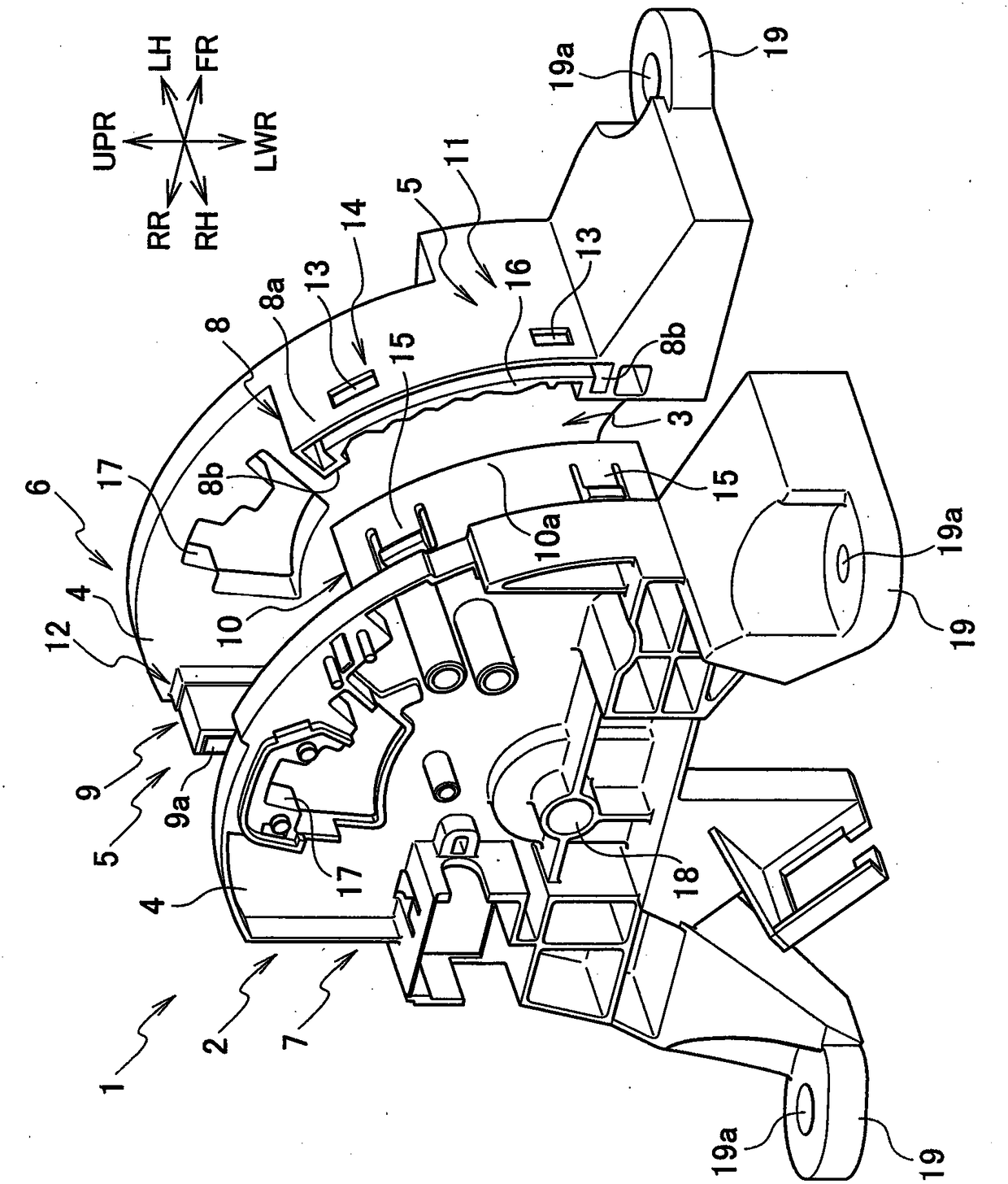
[0018] The shift lever device 1 of the present embodiment shifts the shift lever (not shown) to a plurality of positions set within the swing range to switch an automatic transmission (not shown) to a predetermined position corresponding to each position. range.

[0019] In addition, in the following, the front-back direction, the left-right direction, and the up-down direction will be described with reference to the casing 2 . In the drawing, arrow FR shows the front direction, arrow RR shows the rear direction, arrow RH shows the right direction, arrow LH shows the left direction, arrow UPR shows the upward direction, and arrow LWR shows the downward direction.

[0020] like figure 1 as well as figure 2 As shown, the shift lever device 1 includes a case 2 fixed to a vehicle body of a vehicle (not shown), and a shift lever supported by the ca...


PUM


Abstract

The invention provides a shift lever device including a housing and a shift lever. The housing is separable in the right-left direction at connecting walls. The connecting wall has a fitting portion which protrudes from one of the pair of right and left side walls toward the other side wall and a fitting tube portion which protrudes from the other side wall toward the one side wall and into whichthe fitting portion is fitted. The fitting portion has a fitting-portion main part and an inner fitting part extending inward of the housing from the fitting-portion main part. The fitting tube portion has a fitting-tube-portion main part into which the fitting-portion main part is fitted, and an inner fitting tube part which extends inward of the housing from the fitting-tube-portion main part and into which the inner fitting part is fitted.

Description

technical field [0001] The present invention relates to shift lever devices. Background technique [0002] Conventionally, a shift lever device for operating an automatic transmission of a vehicle is known. [0003] Such a shift lever device includes a case fixed to a vehicle body of a vehicle, and a shift lever swingably supported by the case. As such a shift lever device, there is a mechanism that divides the housing into two parts on the left and right as an independent body, supports the shift lever between the two housings, and combines the two housings (for example, refer to Patent Document 1 ). [0004] prior art literature [0005] Patent Document 1: Japanese Patent Laid-Open No. 2013-199221 [0006] In the shift lever device disclosed in Patent Document 1, both cases are coupled using protrusions and clips. However, there is a problem that it is difficult to ensure the rigidity of the cases in coupling using such protrusions and clips. Contents of the inventio...

Claims


Application Information

Patent Timeline
Patent Type & Authority Applications(China)
IPC IPC(8): F16H59/02
CPCF16H61/24F16H59/10F16H2059/026F16H2061/247F16H59/0278
Inventor 泷川喜博
Owner FUJI KIKO CO LTD
Why Eureka
Try Eureka