Spring reciprocating cutting device

A technology of cutting device and spring device, which is applied in the direction of metal processing, etc., can solve the problems of long cleaning auxiliary time, difficult cleaning and disinfection, impossible use, etc., and achieve the effect of uniform force, convenient sanitation and easy maintenance

Active Publication Date: 2019-08-16
成都庶民科技有限公司 +1
View PDF6 Cites 0 Cited by
  • Summary
  • Abstract
  • Description
  • Claims
  • Application Information

AI Technical Summary

Problems solved by technology

[0004] One of the purposes of the present invention is to solve the above-mentioned deficiencies, and provide a spring-type reciprocating cutting device, in order to solve the complex structure of similar equipment in the prior art, which is impossible to use in the family, especially difficult to clean and disinfect, and takes a long time for cleaning assistance. question

Method used


Image

  • Spring reciprocating cutting device
  • Spring reciprocating cutting device
  • Spring reciprocating cutting device

Examples


Embodiment 1

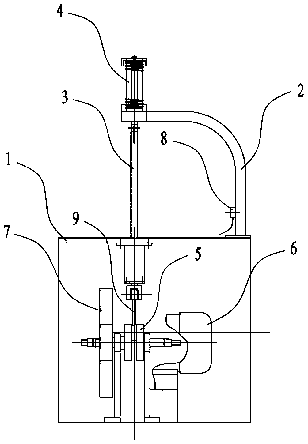
[0029] refer to figure 1 Shown, one embodiment of the present invention is a kind of spring-type reciprocating cutting device, comprises frame 1, needs to install support 2 on the top of frame 1, and needs to install a vertical saw blade 3 on the support 2 movably, this The upper end of saw blade 3 needs to be connected with spring device 4 power, and this spring device 4 also needs to be installed on the frame 1, is used for applying upward pulling force to saw blade when spring device is stretched, to strengthen described The tension of the saw blade as it moves up and down. In addition, the lower end of the aforementioned vertically installed saw blade 3 is also power-connected with the eccentric wheel 5 , and the eccentric wheel 5 is power-connected with the output end of the motor 6 . as figure 1 Shown, the structure of support 2 can be set to L type, promptly one end is installed on the frame 1, and the other end is suspended in the air as free end, and aforementioned ...

Embodiment 2

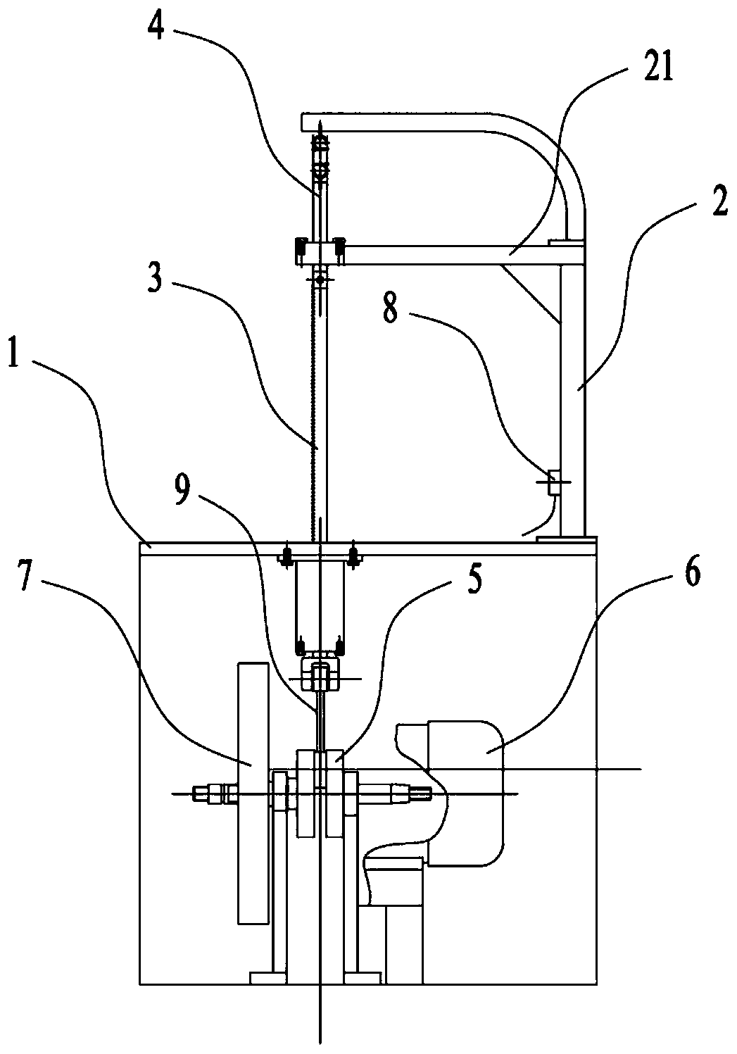
[0036] refer to figure 2 As shown, in another embodiment of the present invention, another implementation of the spring device is disclosed, and the structure of the above-mentioned bracket 2 is improved, specifically, the bracket 2 is still set in an L shape, and then the bracket The middle part of 2 adds a transverse first connecting frame 21, and this first connecting frame 21 is fixedly installed on the support 2, and the above-mentioned spring device 4 is installed between the free end of the support 2 and the first connecting frame 21, and then the The first connecting frame 21 is also set on the outside of the upper end of the saw blade 3, and the material is placed on the upper part of the frame 1. When it is close to the sensor 8, the sensor 8 is triggered, and then the control module controls the deceleration motor to start running and decelerate. The output end of the motor drives the pulley 7 to rotate through the belt, and then the pulley 7 drives the eccentric w...

Embodiment 3

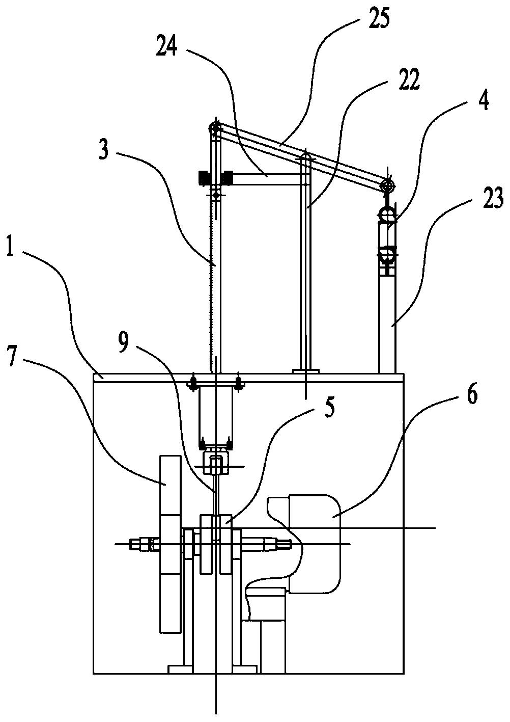
[0038] refer to image 3 As shown, in another embodiment of the present invention, this embodiment discloses another implementation of the spring device, and another structural improvement is made to the above-mentioned bracket 2, specifically as image 3As shown, the above-mentioned bracket 2 is set as a split first support frame 22 and a second support frame 23, and a horizontal second connecting frame 24 is installed on the first supporting frame 22, and the second connecting frame 24 is set on the saw The outside of the upper end of the knife 3, then the above-mentioned spring device 4 is installed on the upper end of the second support frame 23, and finally the upper end of the saw blade 3 is dynamically connected with the spring device 4 through the third connecting frame 25. In addition, the third connecting frame 25 The vicinity of the middle part also needs to be movably installed on the first support frame 22; by installing the spring device 4 on the second support f...


PUM


Abstract

The invention discloses a spring type reciprocating cutting device which comprises a stand, wherein a bracket is mounted at the upper part of the stand; a saw blade is movably mounted on the bracket; the upper end of the saw blade is connected with a spring device; the spring device is mounted on the bracket; and when the spring device is stretched, reverse pulling force is applied to the saw blade, so as to enhance the rigidity of the saw blade during moving. According to the spring type reciprocating cutting device, by the arrangement of the spring device on the stand, the spring device is directly or indirectly connected with the saw blade; and except that the saw blade and a moving rod, a platform and the bracket which are connected to two ends of the saw blade are exposed, other components are all of sealed structures, so that the spring type reciprocating cutting device is easy to clean and disinfect and good in cleaning effect. The spring type reciprocating cutting device is easy to wash, and the cleaning and disinfection auxiliary time is very short.

Description

technical field [0001] The present invention relates to a food processing device, and more specifically, the present invention mainly relates to a spring type reciprocating cutting device. Background technique [0002] All adopt chopping knife (chopping knife) manually to chop meat products with bones such as chicken, duck, spare ribs in the family now; Whether domestic or foreign, this kind of band saw structure is adopted. In industrial applications, this kind of structure has good stability and high efficiency, but it is not suitable for household use. It occupies too much area. The debris is carried to every part of its operation. Regular cleaning and disinfection in industrial production activities, but in households, the cut objects are mostly high-protein and high-fat substances such as beef and mutton bones, fish bones, poultry meat and bones, and frozen foods, which are easy to breed bacteria, which not only affects environmental sanitation, but also Difficult to ...

Claims


Application Information

Patent Timeline
Patent Type & Authority Patents(China)
IPC IPC(8): B26D1/06B26D5/16B26D7/26B26D7/22
CPCB26D1/0006B26D1/06B26D5/16B26D7/22B26D7/2614B26D2001/006B26D2210/02
Inventor 李建
Owner 成都庶民科技有限公司
Why Eureka
Try Eureka