Printed circuit card kit

Inactive Publication Date: 2005-03-17
HON HAI PRECISION IND CO LTD
View PDF4 Cites 0 Cited by
  • Summary
  • Abstract
  • Description
  • Claims
  • Application Information

AI Technical Summary

Benefits of technology

[0008] Accordingly, an object of the present invention is to provide a PC

Problems solved by technology

With the development of the technology, the circuitry of the PCB of the PC card become more and more complex and is easily damaged in use.
When the card is inserted into or removed from the electronic equipment, the card shields tend to become loose and/or separated from one another as the card is subjected to flexing or torsional stresses.
Thus, even after moderate amounts of usage, conventional PC card kits have frequently become structurally loose, and the internal members of the card often become misaligned.
This results in failure of the PC card and de

Method used


Image

  • Printed circuit card kit
  • Printed circuit card kit
  • Printed circuit card kit

Examples


Example

[0017] Reference will now be made in detail to the preferred embodiment of the present invention.

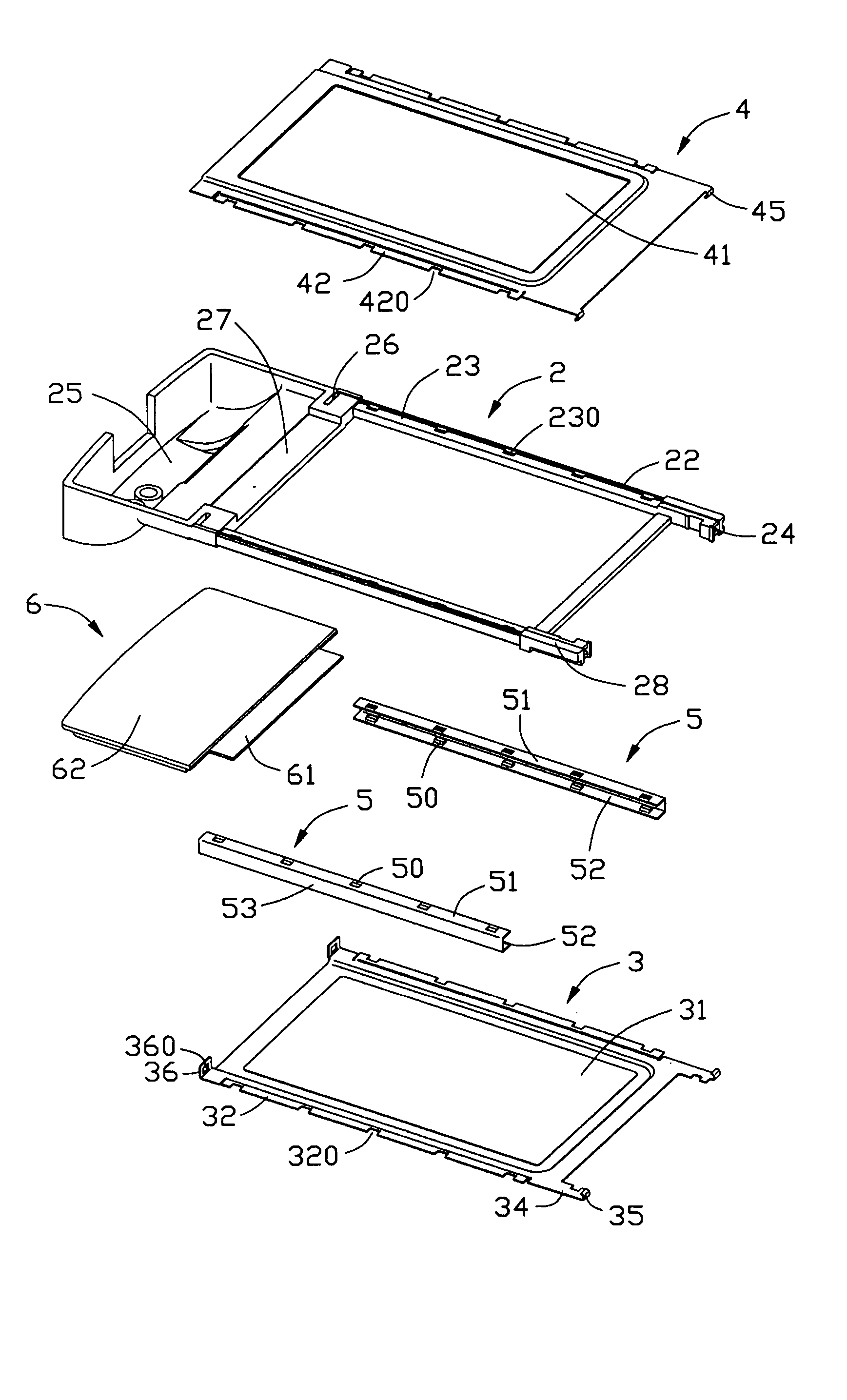
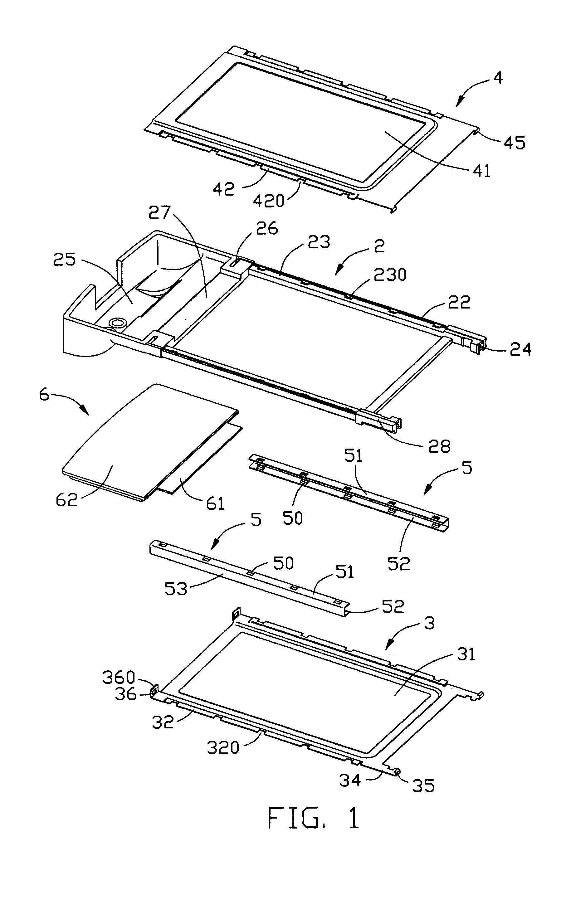
[0018] Referring to FIG. 1 and FIG. 4, a PC card kit 1 in accordance with the present invention comprises a frame 2, a lower cover 3, an upper cover 4, a pair of side covers 5 and an end cover 6.

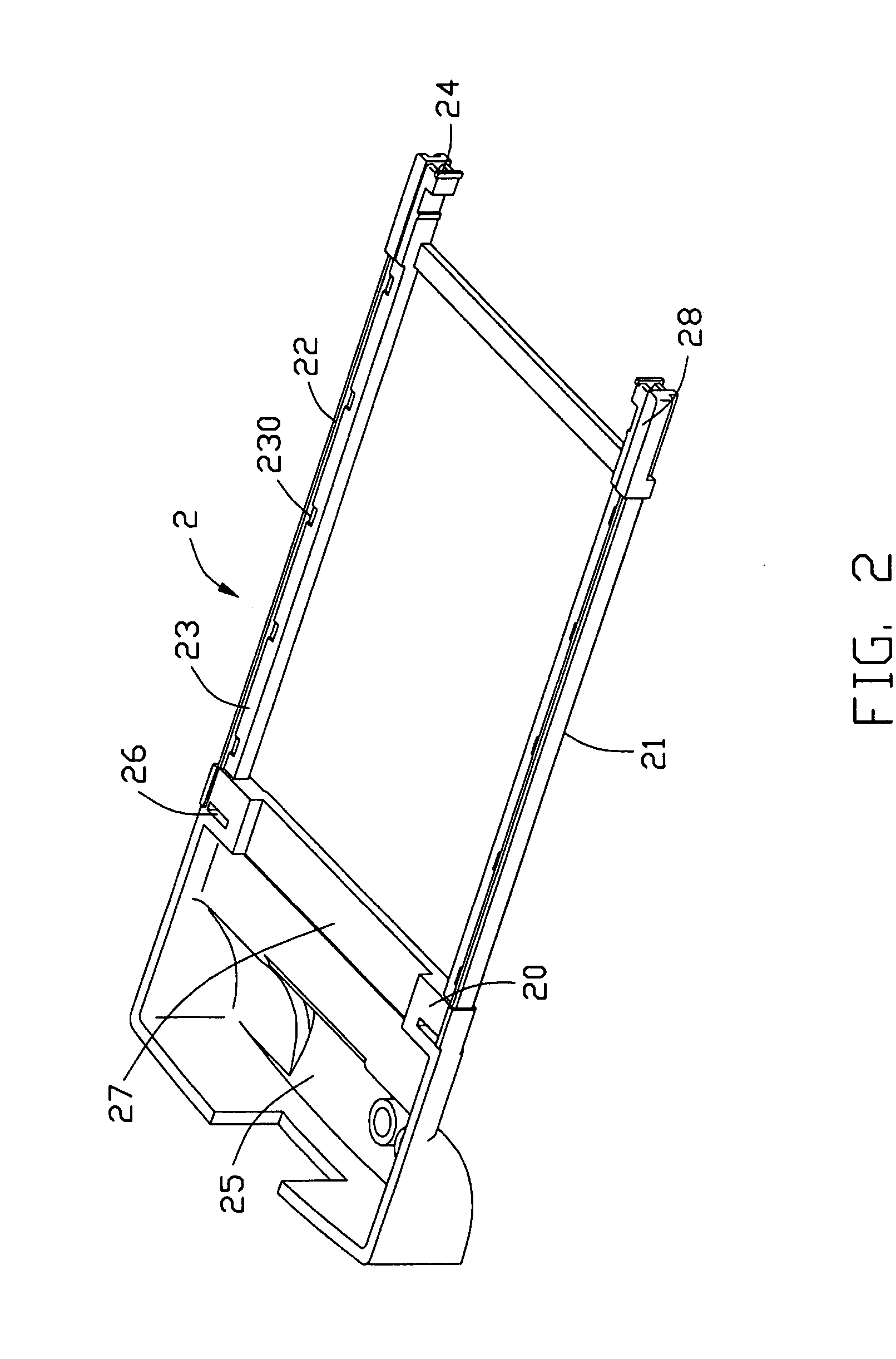
[0019] Referring to FIGS. 1 and 2 in conjunction with FIG. 3, the frame 2 comprises two longitudinal side rails 22, a receiving space 25 for receiving an electrical connector (not show) connected with a printed circuit board (not shown) and a flange 20 between the two side rails 22 and the receiving space 25. The two longitudinal side rails 22 respectively include a top and a bottom surfaces 23, 21 and a plurality of recesses 230 defined in the top and bottom surfaces 23, 21. The receiving space 25 is defined in one end of frame 2. The flange 20 comprises a groove 27, two symmetrical guide slots 26 and a protrusion 29 in each of the guide slots 26. Two arms 28 extend longitudinally out of the s...


PUM


Abstract

A printed circuit card kit (1) comprises a frame (2), an end cover (6), a rectangular lower cover (3), a rectangular upper cover (4), and a pair of side covers (5). The upper cover and the lower cover comprise respectively a pair of edges defining a number of openings (420,320). The frame has two side rails (22) defining a number of recesses (230). The side covers have a number of projections (50) respectively aligned with the openings and recesses. Assembling the end cover to an end of the frame, assembling the upper and lower covers to the frame and assembling the pair of side covers to the side rails of the frame. Therefore, the projections pass the openings and to be retained in the recesses.

Description

BACKGROUND OF THE INVENTION [0001] 1. Field of the Invention [0002] The present invention is related to a printed circuit card kit of a printed circuit card which is used in computers and other electronic equipments. [0003] 2. Description of Related Art [0004] Printed Circuit (PC) cards are widely used in desktop computers, facsimile machines, notebook computers and other electronic equipments. Each of the PC cards generally comprises a printed circuit board (PCB), at least an electrical connector mounted to the PCB and a PC card kit enclosing the PCB and the electrical connector. With the development of the technology, the circuitry of the PCB of the PC card become more and more complex and is easily damaged in use. Further, the PC card is highly desired to provide reliable data in higher transferring speeds, so it is necessary to design a PC card kit that encloses and protects the PCB more reliably. [0005] U.S. Pat. No. 6,320,252 discloses a PC card comprising a PCB, two connector...

Claims


Application Information

Patent Timeline
IPC IPC(8): G06K19/077G11C7/00H01L21/56H05K5/02
CPCH05K5/0273H05K5/0269
Inventor GE, MINGZHANG, GUOHUAZHU, ZIQIANG
Owner HON HAI PRECISION IND CO LTD
Why Eureka
Try Eureka