
Portable steel bar bending equipment

A portable, steel bar technology, applied in the field of hardware processing, can solve the problems of inconvenient use, steel bar bending processing, large bending equipment, etc., and achieve the effects of easy portability, small equipment occupation space, and simple structure.

Inactive Publication Date: 2018-10-26
吴中区甪直磊鑫模具厂
View PDF0 Cites 0 Cited by
  • Summary
  • Abstract
  • Description
  • Claims
  • Application Information

AI Technical Summary

Problems solved by technology

[0002] When on-site production is in progress, it is often encountered that some small tools need to be self-made for use in production. When self-made tools are often encountered in the bending and processing of steel bars, the general special bending equipment is often relatively large and requires a certain amount of work. Operating space, so it is not convenient to use

Method used


Image

  • Portable steel bar bending equipment

Examples


Embodiment Construction

[0014] The preferred embodiments of the present invention will be described in detail below in conjunction with the accompanying drawings, so that the advantages and features of the present invention can be more easily understood by those skilled in the art, so as to define the protection scope of the present invention more clearly.

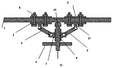
[0015] see figure 1 , the technical solution of the present invention is:

[0016] A portable steel bar bending equipment, the portable steel bar bending equipment includes: a steel bar clamping mechanism, a bending and ejecting mechanism and a connecting force arm, the steel bar clamping mechanism includes a first splint 2 and a second splint The splint 3 is connected with fastening bolts 8 between the splints, and the second splint 3 is connected with the connecting force arm through a movable connection pin 12. A bending ejection mechanism is arranged in the middle of the force arm, and the bending The ejector mechanism includes a threaded ej...


PUM


Abstract

The invention discloses portable steel bar bending equipment. The portable steel bar bending equipment is characterized in that the portable steel bar bending equipment comprises a steel bar clampingmechanism, a bending ejection mechanism and connecting force arms; the steel bar clamping mechanism comprises first clamping plates and second clamping plates, and the clamping plates are connected bybolts; the second clamping plates are movably connected with the connecting force arms, and the bending ejection mechanism is arranged between the force arms; the bending ejection mechanism comprisesa threaded ejector rod and a threaded sleeve matched with the ejector rod, and the threaded sleeve is fixed between the connecting force arms; and a handle and a rotating handle are arranged at the bottom of the ejector rod, and the ejector rod is ejected out forwards from the threaded sleeve. The steel bar bending equipment made according to the structural design occupies a small space, is convenient to carry and can meet the requirements of on-site access at any time.

Description

technical field [0001] The invention relates to the field of hardware processing, in particular to a portable steel bar bending equipment. Background technique [0002] When on-site production is in progress, it is often encountered that some small tools need to be self-made for use in production. When self-made tools are often encountered in the bending and processing of steel bars, the general special-purpose bending equipment is often relatively large and requires a certain amount of work. Operating space, so it is not convenient enough to use. Contents of the invention [0003] The technical problem mainly solved by the present invention is to provide a portable steel bar bending equipment, which can ensure the bending effect, is small in size, easy to carry, and is convenient for on-site operators to use at hand. [0004] In order to solve the above technical problems, a technical solution adopted by the present invention is: 1. A portable steel bar bending equipment...

Claims


Application Information

Patent Timeline
IPC IPC(8): B21D7/06
CPCB21D7/06
Inventor 陈晓升徐明峰戴静
Owner 吴中区甪直磊鑫模具厂
Learn More