Simple assembling and disassembling device for vertical straight arm flange connecting equipment

A connection equipment, vertical technology, applied in the field of disassembly and assembly devices, can solve the problems of high cost, time-consuming and laborious disassembly and assembly, inconvenient and other problems, and achieve the effect of low cost, high efficiency and convenient disassembly and assembly

Inactive Publication Date: 2018-10-26
徐桂根
View PDF0 Cites 2 Cited by
  • Summary
  • Abstract
  • Description
  • Claims
  • Application Information

AI Technical Summary

Problems solved by technology

[0003] The purpose of the present invention is to solve the defects of high cost, time-consuming, laborious and inconvenient disassembly and assembly that need to use lifting equipment when disassembling and assembling the current flange connection equipment, and provide a simple and convenient disassembly of vertical straight arm flange connection equipment. Installation device, its disassembly no longer requires lifting equipment and saves time, effort and money

Method used


Image

  • Simple assembling and disassembling device for vertical straight arm flange connecting equipment
  • Simple assembling and disassembling device for vertical straight arm flange connecting equipment
  • Simple assembling and disassembling device for vertical straight arm flange connecting equipment

Examples


Embodiment 1

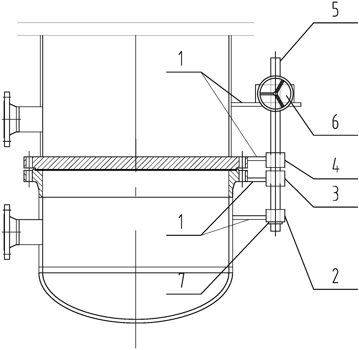
[0020] Such as figure 1 As shown: the flange connection equipment is a new vertical heat exchanger, which includes two parts, the shell side and the tube box. The tube box is on the bottom, and the shell side is on the top. There are the first bushing 4, the second bushing 3 and the first bushing 2, the turbine screw lifter 6 is welded to the shell shell through the connecting plate 1, and the first bushing 4 is welded to the tube plate through the connecting plate 1 On the flange, the second bushing 3 is welded on the pipe box flange through the connecting plate 1, the first bushing 2 is welded on the pipe box cylinder through the connecting plate 1, and the first bushing 4 is provided with a lock nut 7 .

[0021] The new vertical heat exchanger of this embodiment is disassembled and then reassembled for on-site inspection and maintenance as follows:

[0022] 1. The present invention is welded to the shell of the heat exchanger as shown in the figure.

[0023] ② Tighten th...

Embodiment 2

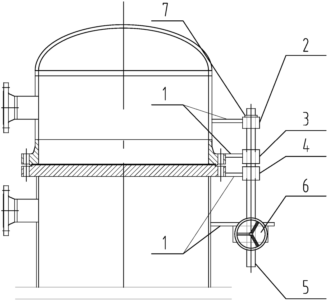
[0029] The flange connection equipment is a new vertical heat exchanger, which includes two parts, the shell side and the tube box, the tube box is on the top, and the shell side is on the bottom.

[0030] The new vertical heat exchanger of this embodiment is dismantled and then reassembled for on-site inspection and maintenance, the process is the same as that of Embodiment 1, except that the handwheel is turned during dismantling to make the pipe box rise slightly to break away from the flange connection stop.

Embodiment 3

[0032] The flange connection equipment is an old vertical heat exchanger, which allows welding, and the others are the same as in Embodiment 1.

[0033] The on-site maintenance of this embodiment is completely the same as that of Embodiment 1 when it is first dismantled and then reassembled.


PUM


Abstract

The invention particularly relates to a simple assembling and disassembling device for vertical straight arm flange connecting equipment. The simple assembling and disassembling device is characterized in that a turbine screw lifter is included, a lifting screw of the turbine screw lifter is a straight rod and is sleeved with three shaft sleeves, and the turbine screw lifter and the inner sides ofthe three shaft sleeves are both provided with connecting plates. The simple assembling and disassembling device has the advantages of being simple in structure, low in cost, flexible and convenientto use and high in efficiency. When the simple assembling and disassembling device is used, hoisting equipment does not need to be used, and the assembling and disassembling cost is greatly lowered. The simple assembling and disassembling device is small in size, the limit from roads, the height of the device and space is low, assembling and disassembling on the site of the device are very convenient, and the assembling and disassembling efficiency can be greatly improved.

Description

technical field [0001] The invention specifically relates to a simple and convenient disassembly device for vertical straight arm flange connection equipment. Background technique [0002] In industrial production, there are many devices that can be disassembled through flange connections. During the assembly or disassembly of the two parts to be connected, lifting equipment (driving, truck crane, back chain, etc.) is required. Especially during the maintenance of the device, due to the limitation of the road, the height of the device, the space, etc., it is extremely troublesome to disassemble and assemble at the device site. Contents of the invention [0003] The purpose of the present invention is to solve the defects of high cost, time-consuming, laborious and inconvenient disassembly and assembly that need to use lifting equipment when disassembling and assembling the current flange connection equipment, and provide a simple and convenient disassembly of vertical str...

Claims


Application Information

Patent Timeline
Patent Type & Authority Applications(China)
IPC IPC(8): B23P19/00
CPCB23P19/00B25B27/16B25B27/023
Inventor 徐桂根
Owner 徐桂根
Why Eureka
Try Eureka