Clock Automatic Needle Loading Machine
A needle loading machine and watch technology, applied in the field of watch production equipment, can solve the problems of not being able to adapt to the mass production requirements of the factory, the time difference of pointer installation, and the depth of pointer pressing, etc., so as to reduce the number of round trips and ensure The effect of time difference and convenient feeding
- Summary
- Abstract
- Description
- Claims
- Application Information
AI Technical Summary
Problems solved by technology
Method used
Image
Examples
Embodiment 1
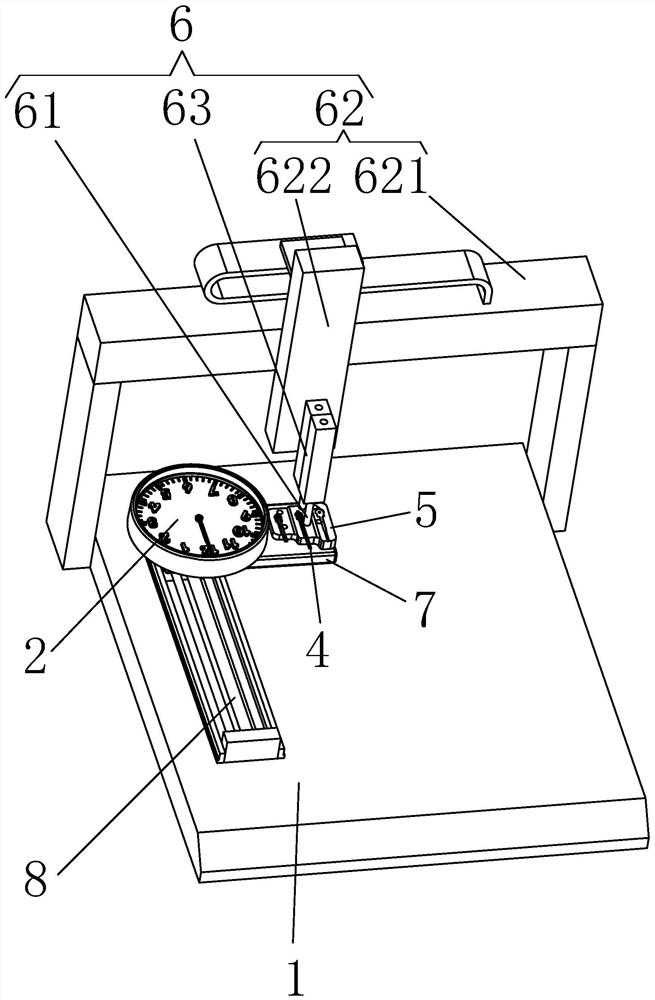
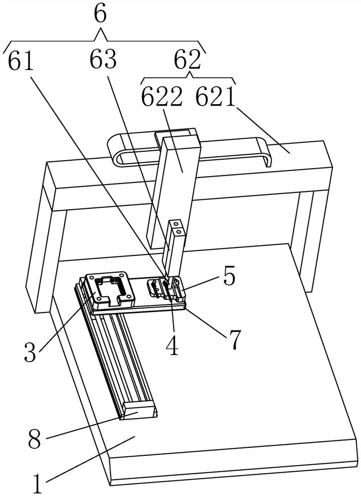
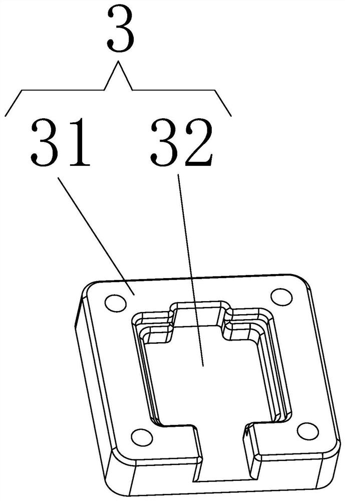
[0031] Such as Figure 1-Figure 5 As shown, it is a watch automatic needle loading machine provided by the present invention, which is characterized in that it includes a base 1, a watch positioning tool 3 arranged on the base 1 for placing the watch 2, and a watch positioning tool 3 arranged on the base 1 for placing the watch. The pointer positioning tool 5 of the pointer 4 and the automatic needle loading mechanism 6 arranged on the base 1 for transporting the pointer 4 on the pointer positioning tool 5 to the top of the clock positioning tool 3 and installed on the clock 2 .
[0032] Such as Figure 1-2 As shown, in order to better transport the pointer on the pointer positioning tool to the top of the clock positioning tool and install it on the clock, the automatic needle loading mechanism 6 includes an adsorption part for absorbing the pointer 4, and is used to drive the adsorption part on the pointer. The moving drive assembly 62 that moves back and forth between the ...
Embodiment 2
[0040] Such as Figure 6 As shown, the difference between Embodiment 2 and Embodiment 1 is that: two groups of mobile drive components 8 are arranged and arranged along the sliding direction of the absorbing parts on the gantry frame, and each group of mobile drive components 2 8 is equipped with a Platform 7, watch positioning tool 3 and pointer positioning tool 5, when one group is assembling the pointer, the other group can be moved to the charging station for charging, which improves the installation efficiency.
Embodiment 3
[0042] Such as Figure 7 As shown, the difference between embodiment 3 and embodiment 2 is: in order to improve the installation efficiency, the watch positioning tool 3 is installed under the automatic needle loading mechanism 6, and the pointer positioning tool 5 is slidably connected to the base 1 and can be positioned on the Move back and forth between the needle loading station side by side with the watch positioning tool 3 and the charging station away from the clock positioning tool 3, and the automatic needle loading machine for watches and clocks also includes a needle for positioning between the pointer positioning tool 5 and the base 1 The mobile driving assembly 3 9 that drives the pointer positioning tool 5 to move back and forth, and the mobile driving assembly 3 9 is connected with the controller. The watch positioning tool 3 is fixedly installed on the base, and the pointer positioning tool 5 is movable, which is convenient for simultaneous loading on both side...
PUM
 Abstract
Description
Claims
Application Information
 - R&D
- Intellectual Property
- Life Sciences
- Materials
- Tech Scout
- Unparalleled Data Quality
- Higher Quality Content
- 60% Fewer Hallucinations
Browse by: Latest US Patents, China's latest patents, Technical Efficacy Thesaurus, Application Domain, Technology Topic, Popular Technical Reports.
© 2025 PatSnap. All rights reserved.Legal|Privacy policy|Modern Slavery Act Transparency Statement|Sitemap|About US| Contact US: help@patsnap.com


