
Current detecting unit for inverter

A current detection unit, inverter technology, applied in electrical components, irreversible DC power input into AC power output, AC power input into AC power output and other directions, can solve the measurement error, difficult to obtain phase current information, etc.

Active Publication Date: 2004-07-21
三电株式会社
View PDF2 Cites 0 Cited by
  • Summary
  • Abstract
  • Description
  • Claims
  • Application Information

AI Technical Summary

Problems solved by technology

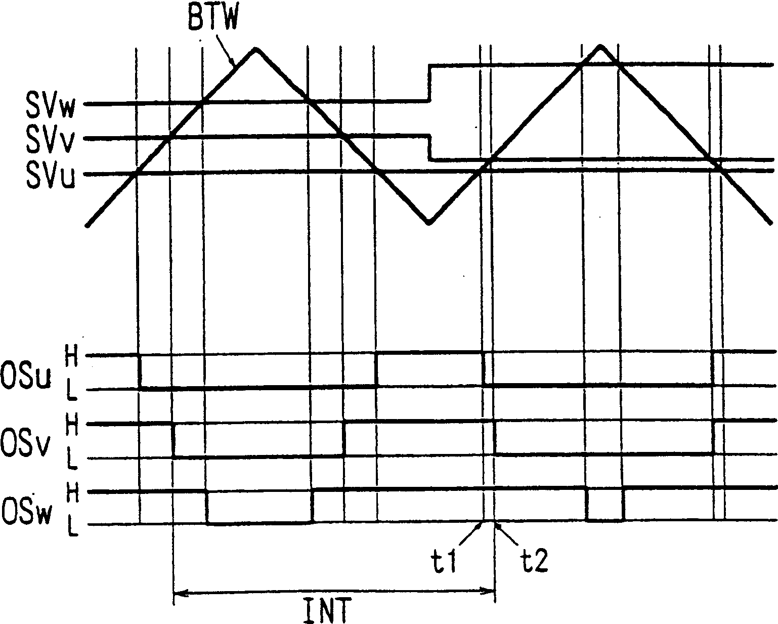
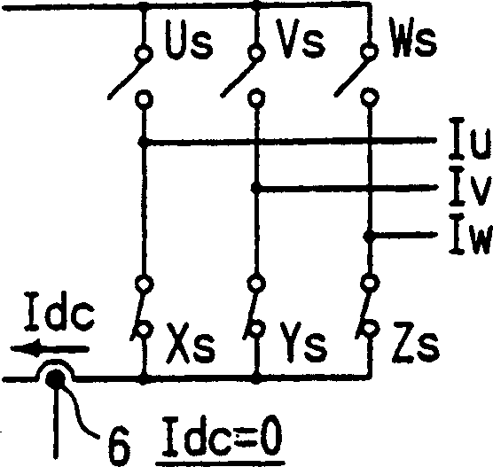
Therefore, the time difference between time t1 and t2 is less than Figure 4 At the time td shown, even if the supply current Idc is measured at the measurement time t1, there may be an error in the measured value
[0011] Furthermore, in the above-mentioned known current detection method, since the power supply current Idc is measured at the moment of transition of the switching situation, if the duty cycle of the respective phase output is changed, the measurement interval INT shown in Fig. 3 is increased or decreased , thus, it is difficult to obtain the phase current information based on the consistent measurement period

Method used


Image

  • Current detecting unit for inverter
  • Current detecting unit for inverter
  • Current detecting unit for inverter

Examples


Embodiment Construction

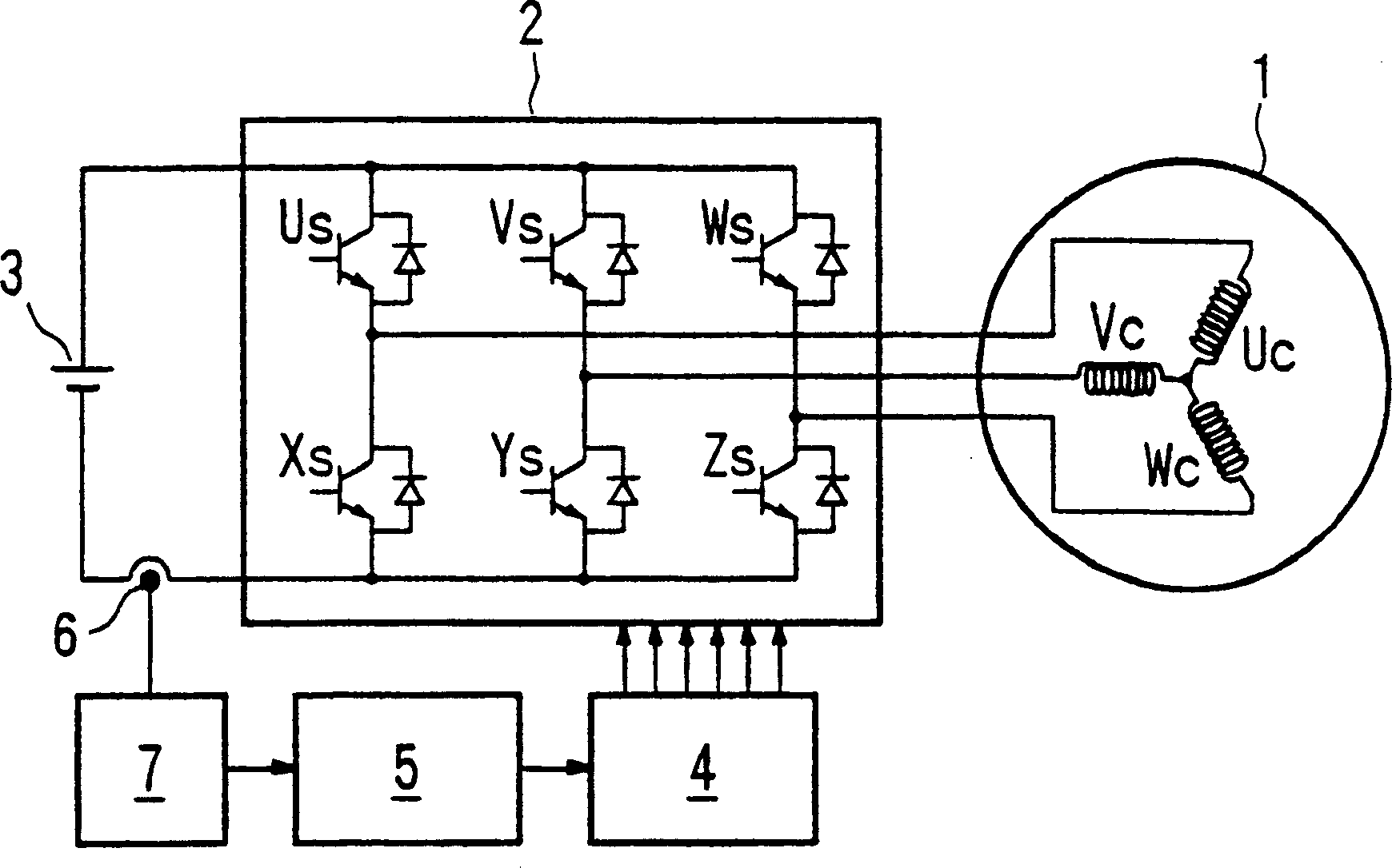
[0034] The motor control unit of the present invention generally has the same functions as the current detection operation in the control unit 5 figure 1 The same circuit configuration is shown. Therefore, if necessary, use the figure 1 The same names and reference numerals in the description will continue to be used in the following description.

[0035] Current sensing according to the present invention can be based on Figure 5 The flowchart shown is implemented. First, the respective phase outputs OSu, OSv and OSw are set using the reference chopping wave BTW and the respective comparison reference signals SVu, SVv and SVw (step S1). Then, the measurement time (a plurality of measurement times) is set (step S2). Measure the power supply current Idc at the set measurement time (step S4), store the power supply current data after A / D conversion (step S5), repeat these operations until the number of repeated measurement times "n" increases to the set measurement times " ...


PUM


Abstract

A current detection unit of an inverter outputs currents to a load, such as a motor includes a device for measuring a DC current flowing in the inverter. The current detection unit also includes a measurement time setting device for setting a measurement time of power source currents at at least one of an uppermost point and a lowest point of a reference chopping wave with a predetermined frequency, and a current phase detection means for detecting at least two phase currents from respective power source currents measured at two or more measurement times sequential to each other. A phased current output from the inverter to a load, such as a motor, may be detected with a high degree of accuracy and at a constant period.

Description

technical field [0001] The present invention relates to a current detection unit of an inverter, wherein the inverter outputs a pseudo three-phase AC power (pseudo three-phase AC power) controlled by pulse width modulation (hereinafter referred to as is "PWM control") converted from DC power. The inverter outputs AC power to a load, such as a motor or a transformer. In particular, the present invention relates to a current detection unit that detects a three-phase current output from an inverter to a load by measuring the current in the inverter. Background technique [0002] figure 1 An example of a known motor control unit using an inverter is depicted. exist figure 1 , the three-phase current is applied from the inverter 2 to the three-phase brushless motor 1 . DC current is applied to the inverter 2 from the DC power source 3 . The inverter 2 is driven by a drive unit 4 which is controlled by a control unit 5 . The DC current applied to the inverter 2 is detected ...

Claims


Application Information

Patent Timeline
Patent Type & Authority Applications(China)
IPC IPC(8): H02M5/45H02M7/48
CPCH02M2001/0009H02M7/53873H02M1/0009
Inventor 广野大辅
Owner 三电株式会社
Learn More