Multifunctional Motor Bearing Sealing Structure

A technology of motor bearings and sealing structures, which is applied in the direction of casings/covers/supports, electromechanical devices, electrical components, etc., can solve problems such as single structure and function, low component utilization, grease suction leakage, etc., to avoid environmental pollution Effects of pollution and resource saving

Active Publication Date: 2019-12-20
CRRC YONGJI ELECTRIC CO LTD
View PDF4 Cites 0 Cited by
  • Summary
  • Abstract
  • Description
  • Claims
  • Application Information

AI Technical Summary

Problems solved by technology

This kind of sealing structure has the following problems: a. The structure has a single function, which only acts as a seal, and cannot balance the air pressure difference between the gearbox and the motor; A good structure only has an oil discharge hole or an oil injection hole on the end cover. The structure is old-fashioned and the utilization rate of components is low; c. The role of the internal cooling air of the motor forms a local large negative pressure on the end face of the inner bearing chamber, which cannot be self-adjusted. As a result, the lubricating grease in the bearing chamber is sucked and leaked, polluting the internal components of the motor, and causing safety hazards; d. When the motor is running at high speed, under the action of high pressure in the gearbox and negative pressure inside the motor, the oil mist can easily enter the bearing chamber and pollute the bearing chamber Grease, damage to bearings

Method used


Image

  • Multifunctional Motor Bearing Sealing Structure
  • Multifunctional Motor Bearing Sealing Structure
  • Multifunctional Motor Bearing Sealing Structure

Examples


Embodiment Construction

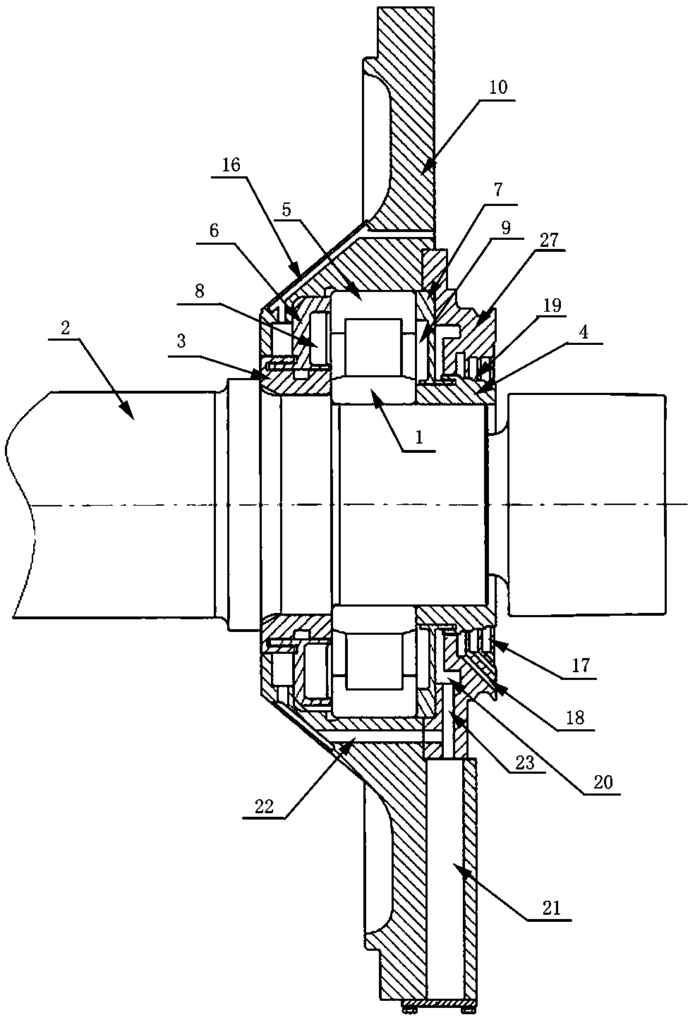
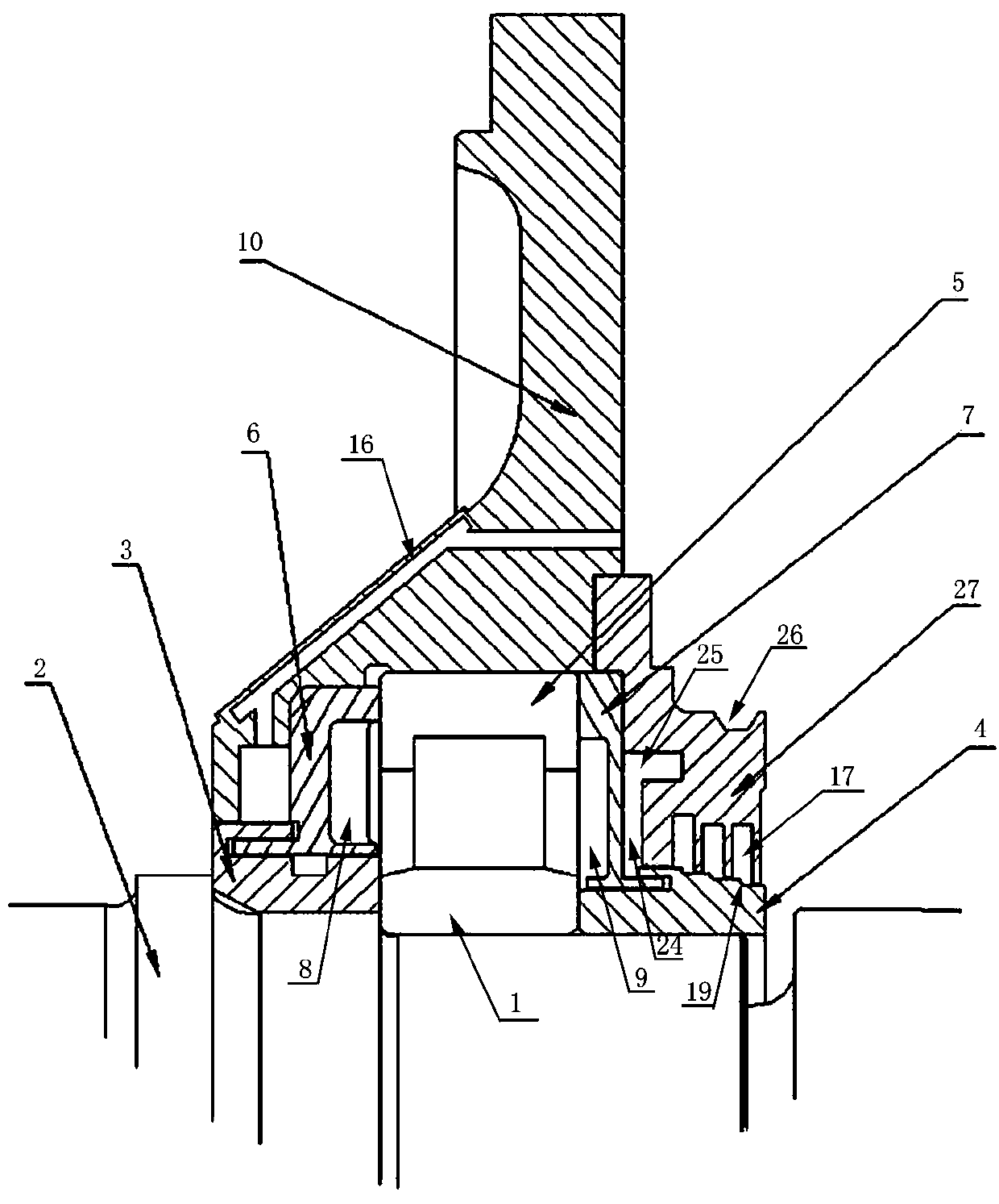
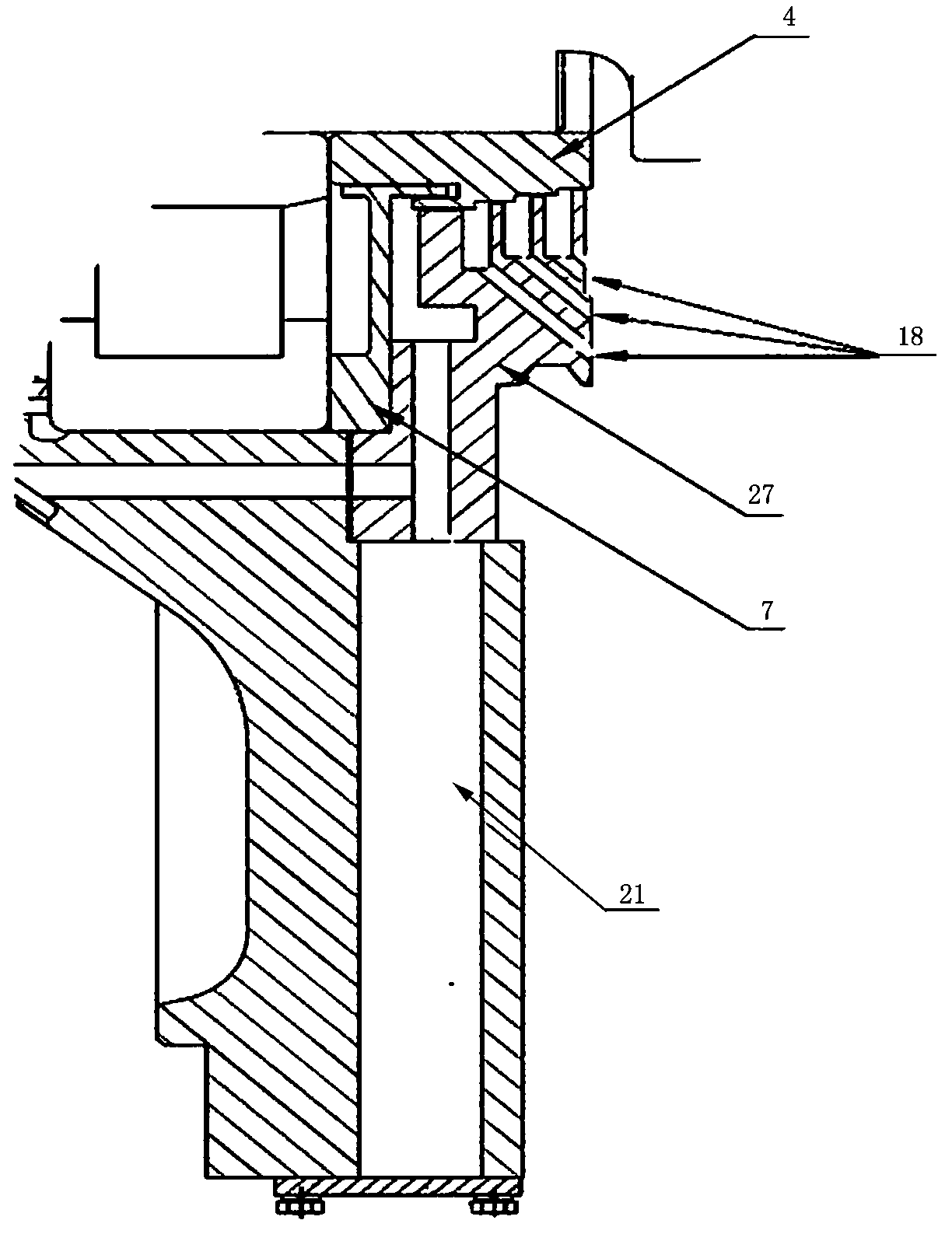
[0017] refer to Figure 1 to Figure 5, the multi-functional motor bearing sealing structure of the present invention includes a shaft sleeve 3 and an outer seal ring 4 which abut against the inner end surface of the bearing inner ring 1 and the outer end surface of the bearing inner ring 1 respectively and are fixed on the rotating shaft 2, the shaft sleeve 3 and the outer sealing ring 4 The outer seal ring 4 axially positions the bearing inner ring 1; it also includes an inner seal ring 6 that abuts on the inner end surface of the bearing outer ring 5 and is labyrinthically sealed with the shaft sleeve 3, and abuts on the outer end surface of the bearing outer ring 5 and is in contact with the outer end surface of the bearing outer ring 5. The outer seal ring 4 is a labyrinth-sealed bearing cover 7, the inner seal ring 6 and the bearing cover 7 are provided with annular recesses facing the bearing to form the inner bearing chamber 8 and the outer bearing chamber 9 respectively...


PUM


Abstract

The present invention relates to fields relating to electric motor bearing sealing structures, and in particular to a multi-functional electric motor bearing sealing structure, aiming at solving the technical problems of single function of the current bearing sealing structure, lubricating grease in a bearing chamber tending to enter an electric motor, and oil mist in a gear box tending to enter the bearing chamber. The following technical solution is mainly used: an end cover is provided with a two-step stepped hole gradually expanding from inside to outside; the end cover is further provided with an air inlet channel with two ends respectively in communication with the outside atmosphere and a second through hole; an outer bearing cover is arranged adjacent to an outer side of a bearing cover; an inner ring of the outer bearing cover is provided with several annular grooves, and each annular groove is in communication with an oil return channel leading to a gear box; an outer ring of an outer sealing ring is provided with annular steps corresponding to the annular grooves; an inner end face of the outer bearing cover is further provided with an oil return cavity; and the end cover is further internally provided with a waste oil storage chamber in communication with the oil return cavity, and an exhaust channel with two ends respectively in communication with the second through hole and the oil return cavity. The present invention is mainly used for sealing a bearing of an electric motor.

Description

technical field [0001] The invention relates to the related field of motor bearing sealing structure, in particular to a multifunctional motor bearing sealing structure. Background technique [0002] The motor bearing sealing structure is a sealing structure set up to prevent dust, water, acid gas and other sundries from entering the bearing, and at the same time prevent the loss of bearing lubricant. A reasonable and reliable motor bearing sealing structure is crucial to the safe operation of the motor. important. [0003] The transmission gear in the gearbox matched with the motor is lubricated by splash lubrication. The large gear is immersed in the lubricating oil, and when it rotates at high speed, the lubricating oil is brought up to lubricate the meshing teeth. Due to the friction between the large gear and the lubricating oil and the meshing gears, the temperature of the lubricating oil rises, and the air pressure in the gearbox rises accordingly. Although there is...

Claims


Application Information

Patent Timeline
Patent Type & Authority Patents(China)
IPC IPC(8): H02K5/16H02K5/128
CPCH02K5/128H02K5/16
Inventor 马千柱郭晏麟张婷李广
Owner CRRC YONGJI ELECTRIC CO LTD
Why Eureka
Try Eureka