Phase-shifting and shifting unit combined permanent magnet synchronous linear motor

A technology of synchronous linear motors and permanent magnet synchronous linear motors, which is applied in the field of permanent magnet synchronous linear motors and unit combination permanent magnet synchronous linear motors, and can solve the problems of large thrust fluctuations of linear motors, affecting the performance of linear motors, and the inability to apply precision requirements, etc. , to achieve strong theoretical significance and engineering practical value, suppress significant thrust fluctuations, and eliminate magnetic field interference

Inactive Publication Date: 2018-10-26
HARBIN UNIV OF SCI & TECH +2
View PDF5 Cites 2 Cited by
  • Summary
  • Abstract
  • Description
  • Claims
  • Application Information

AI Technical Summary

Problems solved by technology

However, due to the cogging effect and end effect of the linear motor, the thrust of the linear motor fluctuates greatly, which affects the performance of the linear motor and cannot be applied to some occasions with high precision requirements. Therefore, measures should be taken to suppress the thrust of the linear motor fluctuation
[0003] At present, scholars at home and abroad have done a lot of work on the suppression of thrust fluctuations of permanent magnet linear motors, mainly including cutting the teeth of the motor, changing the width of the teeth at the side and end of the motor, using semi-closed slots, changing the pole arc coefficient, opening auxiliary slots, and From the control strategy to suppress thrust fluctuations, etc., the process is complicated and the cost is high, and the effect of suppressing thrust fluctuations is also uneven, and there are many defects.

Method used


Image

  • Phase-shifting and shifting unit combined permanent magnet synchronous linear motor

Examples


Embodiment Construction

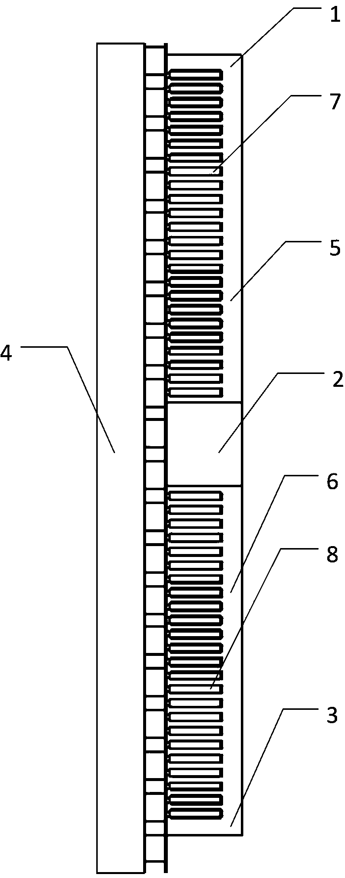
[0020] Such as figure 1 As shown, the motor includes a first unit motor (1), a motor interval (2), a second unit motor (3), a mover (4), a first stator core (5), a second stator core (6 ), the first stator coil (7), the second stator coil (8), and the motor interval (2) are located between the first unit motor (1) and the second unit motor (3).

[0021] The length of the motor interval (2) is 1 / 2t+nT, where t is the tooth pitch of the linear motor, T is the pole pitch of the motor, and n is a positive integer starting from zero. The first unit motor (1) and the second unit motor (3) The structure is exactly the same, the winding arrangement is also the same, the phase difference of the current connected to the first stator coil (7) and the second stator coil (8) is t / T*180°.

[0022] When the linear motor is working, the mover (4) moves linearly in the phase-shifted double-unit motor composed of the first unit motor (1), the motor spacer (2) and the second unit motor (3), Th...


PUM


Abstract

The invention discloses a phase-shifting and shifting unit combined permanent magnet synchronous linear motor, and belongs to the technical field of a linear motor. The phase-shifting and shifting unit combined permanent magnet synchronous linear motor is formed by a first unit motor, a motor spacer, a second unit unit, a mover, a first stator core, a second stator core, a first stator coil and asecond stator coil. A conventional linear motor is split into two unit motors and phase-shifting and shifting are carried out; and by utilizing a superposition principle, thrust ripples respectively generated by two unit motors are reversely superposed to be weakened or eliminated so as to effectively inhibit a thrust ripple of the permanent magnet linear motor. An air or magnetic isolation material is positioned between two adjacent unit motors so as to effectively eliminate magnetic field interference between two unit motors. A plurality of unit motors can also be adopted to be combined in series, and meanwhile, phase-shifting and shifting are carried out, so that an effect of synthesizing a high thrust motor by utilizing low thrust motors can be achieved. The phase-shifting and shiftingunit combined permanent magnet synchronous linear motor has the advantages of simple process, low cost, obvious effect of inhibiting the thrust ripple and the like, and has very high theoretical significance and engineering practical value.

Description

technical field [0001] The invention relates to a permanent magnet synchronous linear motor, in particular to a permanent magnet synchronous linear motor with phase-shifting unit combination. It belongs to the technical field of linear motors. Background technique [0002] Linear motors have played an increasingly important role in recent decades. What makes them superior to rotary motors is that there is no electromagnetic transmission conversion device of any intermediate mechanism, but a device that directly converts electrical energy into mechanical motion, so it is obtained a wide range of applications. Permanent magnet linear synchronous motor has the dual advantages of permanent magnet motor and linear motor, and its small size, fast response and simple structure have broad application prospects. However, due to the cogging effect and end effect of the linear motor, the thrust of the linear motor fluctuates greatly, which affects the performance of the linear motor ...

Claims


Application Information

Patent Timeline
Patent Type & Authority Applications(China)
IPC IPC(8): H02K41/03
CPCH02K41/031
Inventor 周封王福佳郝婷李伟力杨岳刘小可王支业王业彬王瀑权
Owner HARBIN UNIV OF SCI & TECH
Why Eureka
Try Eureka