
Frequency-selective damper valve, and shock absorber and piston having such valve

A damping valve, shock absorber technology, applied in shock absorbers, springs/shock absorbers, shock absorbers, etc., can solve problems such as large space and application difficulties, and achieve stable performance, difficult manufacturing tolerances, and simple design. Effect

Active Publication Date: 2018-10-26
KONI BV
View PDF8 Cites 0 Cited by
  • Summary
  • Abstract
  • Description
  • Claims
  • Application Information

AI Technical Summary

Problems solved by technology

For their part, known one-way frequency-selectable damping valves already require very large spaces, which can make the application of such valves difficult
[0006] For currently known configurations, it is also possible that the individual valves manufactured exhibit a very strong dependence on manufacturing tolerances

Method used


Image

  • Frequency-selective damper valve, and shock absorber and piston having such valve
  • Frequency-selective damper valve, and shock absorber and piston having such valve
  • Frequency-selective damper valve, and shock absorber and piston having such valve

Examples


Embodiment Construction

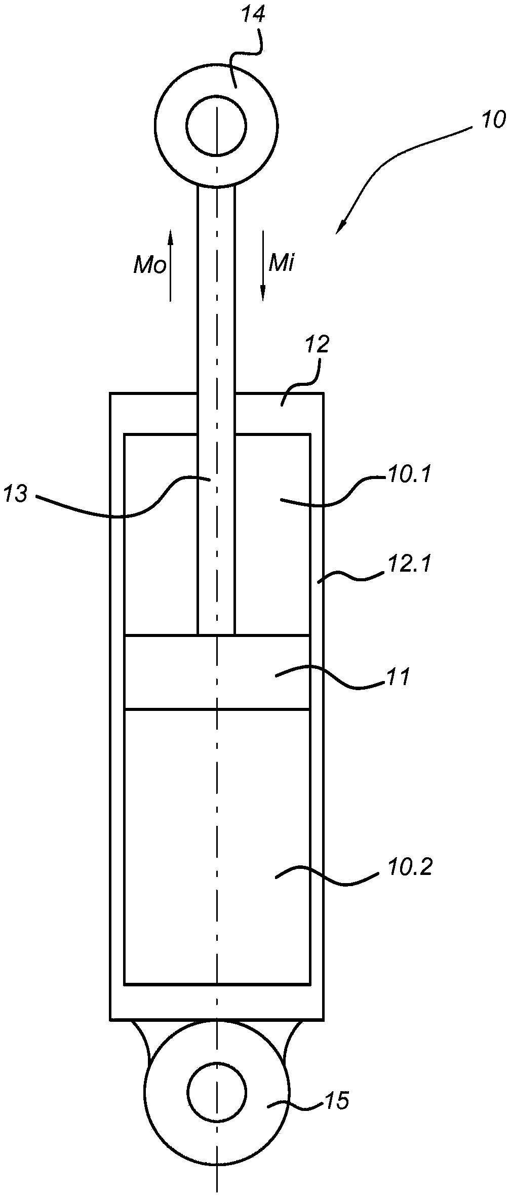
[0079] figure 1A shock absorber or damper 10 according to the invention is shown schematically. The damper includes a cylinder 12 and a piston 11 movable within the cylinder in inward and outward directions relative to the cylinder. The directions of movement of the piston's inward and outward strokes are indicated by arrows labeled Mi and Mo, respectively. The piston seals against the cylindrical wall 12.1 of the cylinder and divides the cylinder into a first or upper cylinder (damping) chamber 10.1 and a second or lower cylinder (damping) chamber 10.2. A piston rod 13 attached to the piston 11 is guided through the top wall of the cylinder 12 in a sealed manner. The damper may be attached by its piston attachment means 14 and cylinder attachment means 15 to eg a component of an automobile to damp relative motion. The damping can be achieved by, for example, the arrangement of the piston 11 influencing the fluid flow between the first cylinder chamber and the second cylind...


PUM


Abstract

A frequency-selective damper valve comprises a controlled flow channel (302, 205, 105, 301) to provide a fluid connection between first and second valve sides; a controlled valve assembly (500) in thecontrolled flow channel; a movable valve body (600) acting on the controlled valve assembly so as to allow changing a flow resistance; and a variable volume chamber (710, 720), the movable valve body(600) interacting with the variable volume chamber (710, 720) such that movement of the movable valve body (600) and a change in volume of the variable volume chamber (710, 720) are interrelated. Thevariable volume chamber (710, 720) comprises an outlet opening (711, 721), in operation, downstream of the controlled valve assembly and does not comprise an opening upstream of the controlled valveassembly with respect to a controlled fluid flow in the controlled flow channel, the outlet opening providing a flow resistance. A fluid pressure upstream of the controlled valve assembly with respectto the controlled fluid flow acts on the movable valve body (600) so as to induce a force on the movable valve member in a direction to decrease a volume of the variable volume chamber by fluid flowfrom the variable volume chamber through the outlet opening (711, 721).

Description

technical field [0001] The present invention relates to a frequency selectable damper valve having a controlled fluid passage and a controlled valve assembly disposed in the controlled fluid passage. Background technique [0002] Dampers or shock absorbers are well known and widely used, for example, in various vehicles such as cars, trucks, buses and trains. Dampers are designed to provide desired damping characteristics between components that move relative to each other. Depending on the specific design of the damper, the damping can be selected to be hard or soft. More advanced dampers have been proposed which provide frequency selective damping characteristics to the damper. Frequency selectable damping valves can be added to the damper to provide the desired frequency selectable damping characteristics. Such a frequency selective damper valve may be added to or incorporated into known damper arrangements to provide additional frequency selectivity. On the other han...

Claims


Application Information

Patent Timeline
Patent Type & Authority Applications(China)
IPC IPC(8): F16F9/512
CPCF16F9/3482F16F9/3485F16F9/16F16F9/5126F16F9/34F16F9/362
Inventor 保罗·德科克
Owner KONI BV
Features
  • Generate Ideas
  • Intellectual Property
  • Life Sciences
  • Materials
  • Tech Scout
  • Unparalleled Data Quality
  • Higher Quality Content
  • 60% Fewer Hallucinations
Learn More