
Bent sectional material pultrusion production traction device and method based on traction rate differential motion

A technology of traction equipment and profiles, applied in the field of pultrusion production traction equipment, can solve problems such as difficulties in pultrusion production, and achieve the effect of simple structure and clear movement principle

Active Publication Date: 2018-10-30
SOUTHEAST UNIV
View PDF6 Cites 1 Cited by
  • Summary
  • Abstract
  • Description
  • Claims
  • Application Information

AI Technical Summary

Problems solved by technology

At present, most pultrusion units are used to produce straight profiles. For curved profiles, especially curved profiles with large curvature radii, it is difficult to perform pultrusion due to the lack of suitable traction equipment.

Method used


Image

  • Bent sectional material pultrusion production traction device and method based on traction rate differential motion
  • Bent sectional material pultrusion production traction device and method based on traction rate differential motion
  • Bent sectional material pultrusion production traction device and method based on traction rate differential motion

Examples


Embodiment 1

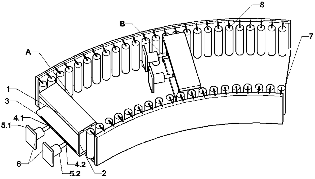
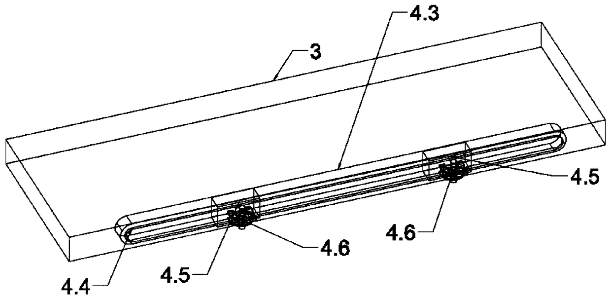
[0019] The traction equipment for the pultrusion production of the fiber reinforced composite curved profile of the present invention is as figure 1 As shown, the traction device is composed of two traction chucks and a rack rail 7, and the traction chuck is composed of a sliding splint 1, a vertical guide rail 2, a fixed splint 3, a first sliding connection 4.1, a second sliding connection 4.2, a second sliding splint A jack 5.1, a second jack 5.2 and a fixed plate 6. The sliding splint 1 can slide up and down along the vertical guide rail 2 to clamp the profile. The fixed splint 3 is connected by the first sliding connector 4.1 and the second sliding Part 4.2 is connected with the first jack 5.1 and the second jack 5.2 respectively, the sliding connecting piece can move relatively linearly along the fixed splint 3, and can rotate relative to the jack, and the jack is connected with the frame through the fixed plate 6 , to prevent the jack from sliding when pushing. The fram...

Embodiment 2

[0023] This embodiment is basically similar to Embodiment 1, and the traction chuck is slightly different, such as Figure 4As shown, a spring 9 is installed between the fixed plate 6 and the fixed splint 3 . The initial state of the spring is the state when the fixed splint is not moving. When the jack pushes the fixed splint to move in a circular curve track, the spring begins to deform. After moving to the farthest distance, the jack returns to oil, no longer applies the jacking force, and the spring begins to retract , can better drive the splint back to its original state.

[0024] According to the different curvature radii of the designed curved profiles, adjusting the size of the plywood, the curvature radius of the frame rail and the pushing speed of the two jacks can be applied to the pultrusion production of different curved profiles.


PUM


Abstract

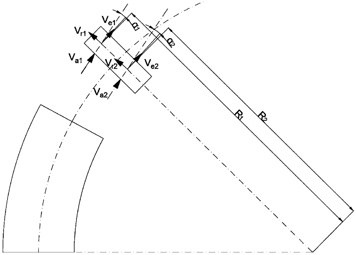
The invention relates to a pultrusion production traction device and method for fiber enhanced composite bent sectional materials based on the traction rate differential motion. The traction device iscomposed of two traction chucks and a rack track. Each traction chuck is composed of a sliding clamping plate, a fixed clamping plate, a vertical guide rail, a sliding connecting piece and a jack. The rack track is a circular curve track and is internally provided with roller shafts, and the motion direction of the traction chucks can be limited. In the traction chuck motion process, through thejack jacking pushing speed differential motion and the rack track limitation, the traction chucks can do plane rotation along the circular curve, and needed bent sectional materials are produced. According to the pultrusion production traction device and method, the motion principle is clear, the equipment structure is simple and feasible, and the pultrusion production traction device and method can be applicable to pultrusion production of bent sectional materials different in radius.

Description

technical field [0001] The invention relates to a traction device for pultrusion production of curved profiles of fiber-reinforced composite materials based on differential traction speed, and belongs to the field of fiber-reinforced composite material structures. Background technique [0002] The pultrusion process is a common process technology in the production of FRP profiles. Under the traction of power machinery, the resin-impregnated reinforcing material will pass through the heated molding cavity to form various designed profiles in a short period of time. It has incomparable characteristics of other processes, showing Strong vitality, the FRP profiles produced by the pultrusion process are light, high-strength, compact in structure, have good aging resistance, insulation and designability, and can achieve high dimensional stability. [0003] The pultrusion unit is generally composed of yarn creel, felt frame, dipping tank, preforming mold, forming mold and heating ...

Claims


Application Information

Patent Timeline
Patent Type & Authority Applications(China)
IPC IPC(8): B29C70/52
CPCB29C70/521B29C70/527
Inventor 万水郑涛孙虎平徐杰杨湛周鹏苏强朱营博徐皓甜
Owner SOUTHEAST UNIV
Learn More