A Cube-Rod Mechanism Realizing the Rotation of Ball-like Joints with Three Degrees of Freedom in Space by Linear Drive

A linear drive, degree of freedom technology, applied in the field of robotics, can solve problems such as complex calculations and poor decoupling, and achieve the effects of improved motion performance, light structure, and convenient motion.

Active Publication Date: 2016-01-20
NANJING UNIV OF AERONAUTICS & ASTRONAUTICS
View PDF7 Cites 0 Cited by
  • Summary
  • Abstract
  • Description
  • Claims
  • Application Information

AI Technical Summary

Problems solved by technology

At present, the design of ball joints has a certain complexity, such as the three-degree-of-freedom spherical space robot wrist designed by Deng Zongquan and others (public number: CN102029614A), and the movements of each degree of freedom will be coupled with each other; especially the use of straight lines In the method of driving to realize three-degree-of-freedom joint rotation, multiple linear drive inputs are coupled to each other, such as a space three-degree-of-freedom parallel robot structure with a bracket and three branches designed by Liu Xinjun et al. (public number: CN1267587A) A three-degree-of-freedom platform parallel robot structure designed by Fang Yuefa and others for spherical rotation (public number: CN1417003A); and in a three-degree-of-freedom ball joint driven by flexible cables such as ropes in parallel, the motion input of each rope is related to the ball joint The three rotation angles have a coupling problem, and its decoupling is poor, and the calculation is more complicated. For example, a flexible cable-driven three-degree-of-freedom parallel mechanism composed of three sets of drive units and a motion platform designed by Zhao Mingyang et al. (public number: CN1250374C) )

Method used


Image

  • A Cube-Rod Mechanism Realizing the Rotation of Ball-like Joints with Three Degrees of Freedom in Space by Linear Drive
  • A Cube-Rod Mechanism Realizing the Rotation of Ball-like Joints with Three Degrees of Freedom in Space by Linear Drive
  • A Cube-Rod Mechanism Realizing the Rotation of Ball-like Joints with Three Degrees of Freedom in Space by Linear Drive

Examples


Embodiment Construction

[0031] Below in conjunction with accompanying drawing and specific embodiment the present invention is described in further detail:

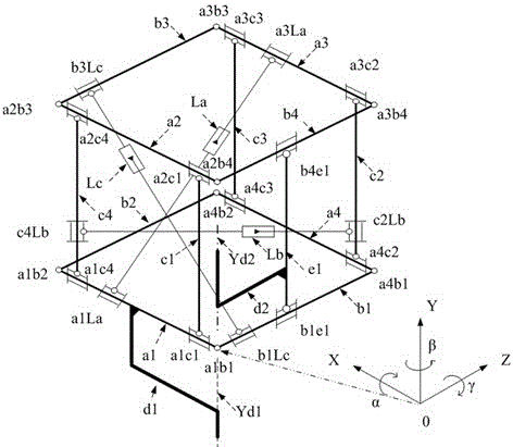
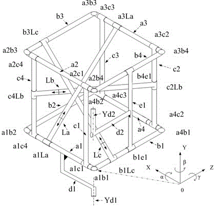
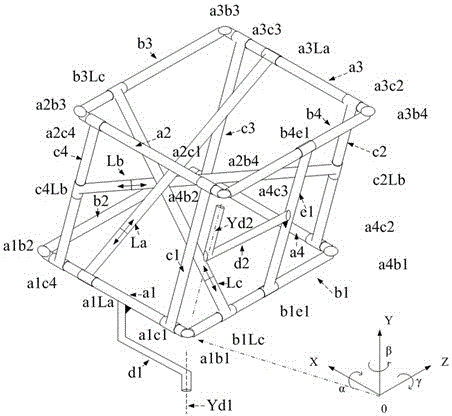
[0032] combine figure 1 , 2 , 3. This embodiment is a linear drive to realize the three-degree-of-freedom spherical joint rotation of the cube rod mechanism, including: coordinate system XYZ, ball joint angle αβγ, X-axis first rigid body a1, X-axis second rigid body a2, X-axis third rigid body a3, X-axis fourth rigid body a4, Y-axis first rigid body c1, Y-axis second rigid body c2, Y-axis third rigid body c3, Y-axis fourth rigid body c4, Z-axis first rigid body b1, Z Axis second rigid body b2, Z axis third rigid body b3, Z axis fourth rigid body b4, first base d1, second base d2, auxiliary rigid body e1, first telescopic rod La, second telescopic rod Lb, third Telescopic rod Lc, first hinge point a1b1 on XZ1 plane, second hinge point a4b1 on XZ1 plane, third hinge point a4b2 on XZ1 plane, fourth hinge point a1b2 on XZ1 plane, first hinge point...


PUM


Abstract

The invention discloses a cube rod mechanism achieving space three-freedom-degree class ball joint rotation through liner driving, and belongs to the technical field of robots. The cube rod mechanism comprises an X-axis first rigid body a1, an X-axis second rigid body a2, an X-axis third rigid body a3, an X-axis fourth rigid body a4, a Y-axis first rigid body c1, a Y-axis second rigid body c2, a Y-axis third rigid body c3, a Y-axis fourth rigid body c4, a Z-axis first rigid body b1, a Z-axis second rigid body b2, a Z-axis third rigid body b3, a Z-axis fourth rigid body b4, a first base d1, a second base d2, an auxiliary rigid body e1, a first telescopic rod La, a second telescopic rod Lb and a third telescopic rod Lc. The cube rod mechanism is simple in structure, strong in decoupling performance, and simple, clear and reliable in motion.

Description

technical field [0001] The invention belongs to the application field of robot technology, and in particular relates to a cubic rod mechanism which is driven by a straight line to realize the rotation of a ball joint with three degrees of freedom in space. . Background technique [0002] Bionic footed robot is one of the most cutting-edge topics in the field of robot research today. It integrates many disciplines such as machinery, electronics, computers, materials, sensors, control technology and artificial intelligence, reflecting a country's intelligence and automation research. At the same time, as an important symbol of a country's high-tech strength, developed countries have invested heavily in research in this field. [0003] The bionic legged robot with hydraulic drive (hydraulic cylinder linear drive) has high load capacity and superior mobility, and will have a huge demand background in special and complex environments such as military, mountain rescue, and forest...

Claims


Application Information

Patent Timeline
Patent Type & Authority Patents(China)
IPC IPC(8): B25J9/00
Inventor 俞志伟郭策沈丹妮汪中原刘蕊王鹏孙功勋戴振东
Owner NANJING UNIV OF AERONAUTICS & ASTRONAUTICS
Why Eureka
Try Eureka