
Engineering vehicle

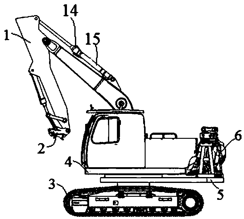
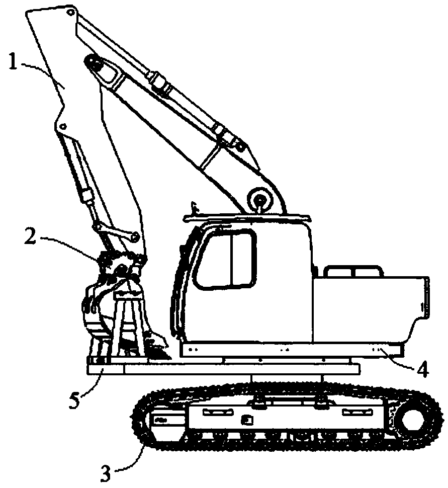
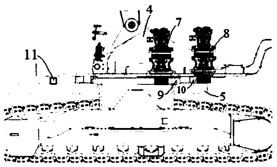
A technology for engineering vehicles and frames, which is applied in construction, mechanically driven excavators/dredgers, earthmoving machines/shovels, etc., and can solve problems such as affecting operation efficiency, occupation, and excessive rescue time.

Pending Publication Date: 2018-10-30
JIANGSU XCMG CONSTR MASCH RES INST LTD
View PDF19 Cites 2 Cited by
  • Summary
  • Abstract
  • Description
  • Claims
  • Application Information

AI Technical Summary

Problems solved by technology

However, in some special cases, such as emergency rescue, etc., the operating arm needs to frequently replace the operating tools in a short period of time according to different working conditions, which requires this type of engineering vehicle to carry a variety of tools
[0003] Most of the various machines and tools of construction vehicles are fixed on the frame by ropes, slings, etc. When the machines need to be replaced, they need to be disassembled and installed manually, which seriously affects the operation efficiency and takes up too much rescue time
However, various tools of some engineering vehicles need to be equipped with special auxiliary vehicles for transportation, which is costly and reduces the application range of engineering vehicles.

Method used


Image

  • Engineering vehicle
  • Engineering vehicle
  • Engineering vehicle

Examples


Embodiment Construction

[0028] The following will clearly and completely describe the technical solutions in the embodiments of the present invention with reference to the accompanying drawings in the embodiments of the present invention. Obviously, the described embodiments are only some, not all, embodiments of the present invention. The following description of at least one exemplary embodiment is merely illustrative in nature and in no way taken as limiting the invention, its application or uses. Based on the embodiments of the present invention, all other embodiments obtained by persons of ordinary skill in the art without creative efforts fall within the protection scope of the present invention.

[0029] The relative arrangements of components and steps, numerical expressions and numerical values ​​set forth in these embodiments do not limit the scope of the present invention unless specifically stated otherwise. At the same time, it should be understood that, for the convenience of descriptio...


PUM


Abstract

The invention discloses an engineering vehicle. The engineering vehicle comprises a vehicle rack, an operating arm arranged on the vehicle rack and a mechanical tool platform, and the mechanical toolplatform is arranged on the vehicle rack and is provided with at least two mechanical tools. The engineering vehicle is provided with a working state and a mechanical tool replacing state, and relative positions between the mechanical tool platform and the operating arm are changeable to make the operating arm be located above the mechanical tool platform and corresponding to the position of the mechanical tool to be replaced of the at least two mechanical tools in the mechanical tool replacing state. According to the engineering vehicle, the vehicle rack is provided with the mechanical tool platform specifically used for placing the mechanical tools, furthermore, the relative positions between the mechanical tool platform and the operating arm are changeable, thus when the mechanical tools need to be replaced, only the operating arm needs to be located above the mechanical tool platform and correspond to the position of the mechanical tool to be replaced so that the operating arm canbe connected with the mechanical tool to be replaced, the mechanical tool replacing time is reduced, the operating efficiency is effectively improved, and the whole mechanical tool replacing process has low requirements for the replacing site, so that the applicability range of the engineering vehicle is broadened.

Description

technical field [0001] The invention relates to the technical field of engineering machinery, in particular to an engineering vehicle. Background technique [0002] With the development of excavator technology and the continuous innovation of equipment, the operating arm of the excavator can be equipped with various equipment such as breaker, hydraulic shear, stone grabber, compactor, rock saw, etc. to meet different operating needs. In general, the working arm will use this tool to work for a long time after changing one tool without frequent replacement of other tools. However, in some special cases, such as emergency rescue, the operating arm needs to frequently replace the working tools in a short period of time according to different working conditions, which requires such engineering vehicles to carry multiple tools. [0003] Most of the various machinery and tools of construction vehicles are fixed on the frame by ropes and slings. When the machinery needs to be repl...

Claims


Application Information

Patent Timeline
IPC IPC(8): E02F3/96E02F3/358E02F9/26
CPCE02F3/358E02F3/96E02F3/964E02F9/265
Inventor 赵斌管培鹏李军
Owner JIANGSU XCMG CONSTR MASCH RES INST LTD
Learn More