Low-energy-consumption and high-efficiency gear automatic cleaning equipment

A high-efficiency, automatic cleaning technology, applied in cleaning methods and utensils, cleaning methods using liquids, chemical instruments and methods, etc., can solve the problems of high energy consumption, low work efficiency, and many power parts, and achieve low energy consumption Effect

Inactive Publication Date: 2018-11-02
ANHUI SANSHAN MACHINERY MFG
View PDF0 Cites 0 Cited by
  • Summary
  • Abstract
  • Description
  • Claims
  • Application Information

AI Technical Summary

Problems solved by technology

However, the existing cleaning device not only has many power parts, but also consumes a lot of energy, and cannot perform assembly line work, and the work efficiency is low, so it needs to be improved urgently.

Method used


Image

  • Low-energy-consumption and high-efficiency gear automatic cleaning equipment

Examples


Embodiment Construction

[0011] Below, the technical solution of the present invention will be described in detail through specific examples.

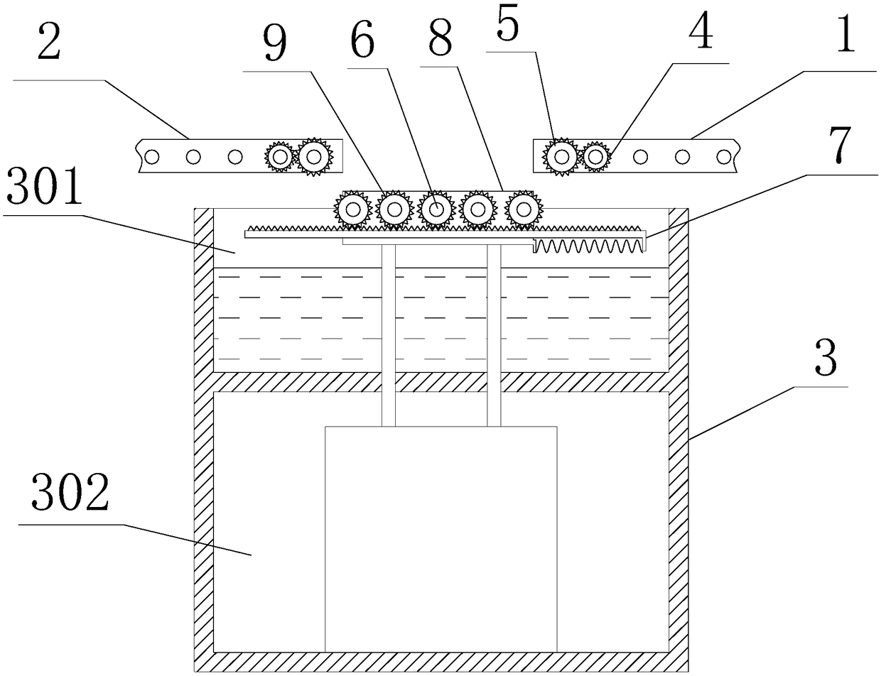
[0012] Such as figure 1 as shown, figure 1 It is a structural schematic diagram of a low-energy-consuming high-efficiency gear automatic cleaning equipment proposed by the present invention.

[0013] refer to figure 1 , an automatic cleaning device with low energy consumption and high efficiency proposed by the embodiment of the present invention, including: an incoming mechanism 1 and an outgoing mechanism 2 for conveying workpieces, and a mechanism located under the incoming mechanism 1 and outgoing mechanism 2 for In the cleaning tank 3 for workpiece cleaning, wherein:

[0014] Both the input mechanism 1 and the output mechanism 2 include several arranged transmission rollers and a power unit for driving the transmission rollers to rotate synchronously and in the same direction to realize the workpiece transmission action; among the transmission rollers,...


PUM


Abstract

The invention discloses low-energy-consumption and high-efficiency gear automatic cleaning equipment. The low-energy-consumption and high-efficiency gear automatic cleaning equipment comprises a conveying-in mechanism, a conveying-out mechanism and a cleaning tank, wherein each of the conveying-in mechanism and the conveying-out mechanism comprises a plurality of conveying rollers and power units;the conveying rollers are arranged in an arrayed manner; the power units are used for driving the conveying rollers to rotate; among the different conveying rollers, a driving gear fixedly assembledwith at least one conveying roller is arranged on the at least one conveying roller; a driven gear rotationally assembled with the other conveying roller is arranged on the other conveying roller; thedriven gear is engaged with the driving gear; a cleaning room and an equipment room are formed in the cleaning tank; a material supporting mechanism is arranged in the cleaning room and comprises a plurality of roller drums, a rack and a supporting frame; the roller drums are arranged in an arrayed manner; the rack is located at the lower part of each roller drum; the supporting frame is used forsupporting each roller drum and the rack; transmission gears which are fixedly assembled with each roller drum and are engaged with the rack are arranged at the two ends of each roller drum; and a driving mechanism used for driving the material supporting mechanism to move up and down is installed in the equipment room. The working efficiency is high, and the energy consumption is low.

Description

technical field [0001] The invention relates to the technical field of gear production and processing, in particular to an automatic gear cleaning device with low energy consumption and high efficiency. Background technique [0002] In the mechanical and electrical industry, gears are widely used. Gears are toothed mechanical parts that can mesh with each other, and play an important role in mechanical transmission and the entire mechanical field. Dirty gears are likely to cause uneven meshing, poor precision, or deformation. Therefore, the cleaning of precision mechanical parts such as gears is very necessary. However, the existing cleaning device not only has many power parts, but also consumes a lot of energy, and cannot perform assembly line work, and the work efficiency is low, which needs to be improved urgently. Contents of the invention [0003] Based on the technical problems in the above-mentioned background technology, the present invention proposes an automat...

Claims


Application Information

Patent Timeline
Patent Type & Authority Applications(China)
IPC IPC(8): B08B3/04B08B13/00
CPCB08B3/04B08B13/00
Inventor 唐漪崑
Owner ANHUI SANSHAN MACHINERY MFG
Why Eureka
Try Eureka