
Panel manufacturing method with decorative surface

A technology for decorating surfaces and plates, applied in metal processing, etc., can solve the problems of lack of height and drilling angle adjustment, low degree of automation, excessive manpower operation, etc., to improve drilling efficiency, high degree of automation, and easy to use Effect

Inactive Publication Date: 2018-11-02
广州凡凡贸易有限公司
View PDF6 Cites 0 Cited by
  • Summary
  • Abstract
  • Description
  • Claims
  • Application Information

AI Technical Summary

Problems solved by technology

[0002] Decorative panels are widely used in the field of modern home decoration. However, in order to meet the actual installation requirements in the processing and production of these decorative panels, drilling operations are required. The traditional panel drilling device has a low degree of automation and requires too much manual operation. Its operation is difficult and inefficient. At the same time, it does not have height and drilling angle adjustment. It has great limitations and has great disadvantages. It needs to be improved.

Method used


Image

  • Panel manufacturing method with decorative surface
  • Panel manufacturing method with decorative surface

Examples


Embodiment Construction

[0022] All features disclosed in this specification, or steps in all methods or processes disclosed, may be combined in any manner, except for mutually exclusive features and / or steps.

[0023] Any feature disclosed in this specification (including any appended claims, abstract and drawings), unless expressly stated otherwise, may be replaced by alternative features which are equivalent or serve a similar purpose. That is, unless expressly stated otherwise, each feature is one example only of a series of equivalent or similar features.

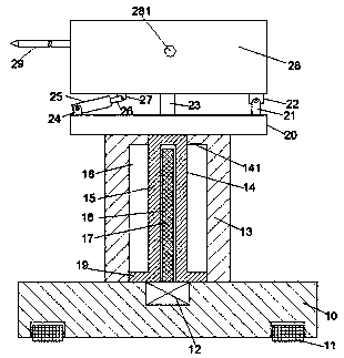
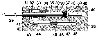
[0024] Such as Figure 1-2 As shown, a panel equipment with a decorative surface of the device of the present invention includes a base 10, a pillar 13 fixedly arranged on the top of the base 10, and a frame body 28 arranged above the top of the pillar 13, the pillar The top of 13 is provided with a support plate 20, and the center position of the top of the support plate 20 is fixed with a support platform 23. The top of the support platform...


PUM


Abstract

The invention discloses panel equipment with a decorative surface. The panel equipment comprises a base, a supporting column fixedly arranged on the top of the base and a rack body arranged above thetop of the supporting column, wherein a supporting plate is arranged on the top of the supporting column; a supporting table is fixedly arranged in the central position of the top of the supporting plate; the top of the supporting table leans against the end surface of the top of the rack body; a first connecting arm and a second connecting arm are separately arranged on the end surfaces on the top of the supporting table on the left and right side of the supporting table; a first connecting block and a second connecting block are fixedly arranged on two sides of the bottom end surfaces of therack body, separately; a hydraulic cylinder is hinged and mounted to the first connecting arm; a hydraulic rod of the hydraulic cylinder is hinged to the first connecting block; a second connecting arm is hinged and mounted to the second hinge block; a sliding cavity opened leftward is formed in the rack body an extended manner left and right; and a sliding block is slidably mounted in the sliding cavity.

Description

technical field [0001] The invention relates to the technical field of home decoration, in particular to a method for manufacturing a plate with a decorative surface. Background technique [0002] Decorative panels are widely used in the field of modern home decoration. However, in order to meet the actual installation requirements in the processing and production of these decorative panels, drilling operations are required. The traditional panel drilling device has a low degree of automation and requires too much manual operation. Its operation is difficult and inefficient. At the same time, it does not have height and drilling angle adjustment. It has great limitations and has great disadvantages, which needs to be improved. Contents of the invention [0003] Aiming at the deficiencies of the above-mentioned technologies, the present invention proposes a method for manufacturing a plate with a decorative surface. [0004] A board equipment with a decorative surface of...

Claims


Application Information

Patent Timeline
Patent Type & Authority Applications(China)
IPC IPC(8): B26F1/16B26D7/26
CPCB26D7/2628B26F1/16
Inventor 程丹秋
Owner 广州凡凡贸易有限公司
Learn More