Plunger hydraulic cylinder with oil being fed through middle position

A hydraulic cylinder and oil feeding technology, which is applied in the field of plunger hydraulic cylinders, can solve the problems affecting the use of single-acting plunger hydraulic cylinders, affecting the installation of single-acting plunger hydraulic cylinders, etc., so as to eliminate the phenomenon of slowing down or stagnation, and movement Uniform and smooth effect

Pending Publication Date: 2018-11-06
江阴市洪腾机械有限公司
View PDF0 Cites 0 Cited by
  • Summary
  • Abstract
  • Description
  • Claims
  • Application Information

AI Technical Summary

Problems solved by technology

[0002] The existing single-acting plunger hydraulic cylinder is an executive element of the hydraulic system. It uses hydraulic oil as the working medium. It includes a piston rod, cylinder body, guide sleeve, cylinder head, cylinder bottom, piston and oil inlet joint. There is a cavity, the cylinder bottom is set at the rear end of the cylinder body, the cylinder head is set at the front end of the cylinder body, the guide sleeve is set in the cylinder body at the rear side of the cylinder head, the piston is set in the cavity in the cylinder body, and the piston guides the cavity Divided into a rod cavity and a rodless cavity; one end of the piston rod passes through the cylinder and the guide sleeve and extends into the cavity of the cylinder body to connect with the piston. The oil inlet joint is set outside the rear end of the cylinder body, and the oil inlet joint directly communicates with the cavity ; Since the oil inlet connector of the single-acting plunger hydraulic cylinder is set outside the rear end of the cylinder body, due to the different structures of some special vehicles, when installing the single-acting plunger hydraulic cylinder, the position of the oil inlet connector will affect the single-acting column. The installation of the piston hydraulic cylinder, which affects the use of the single-acting piston hydraulic cylinder

Method used


Image

  • Plunger hydraulic cylinder with oil being fed through middle position

Examples


Embodiment Construction

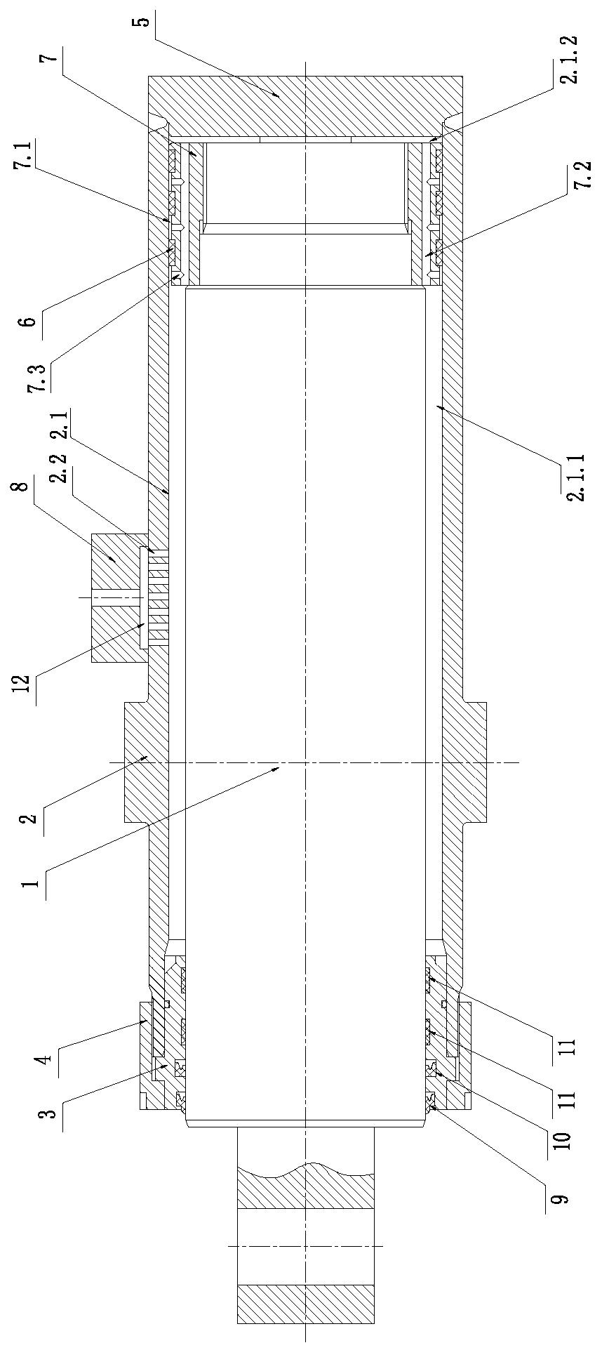
[0008] Such as figure 1 As shown, a plunger hydraulic cylinder with oil inlet in the middle is characterized in that it includes a plug rod 1, a cylinder body 2, a guide sleeve 3, a cylinder head 4, a cylinder bottom 5, a support ring 6, a piston 7, and an oil inlet joint 8. Dustproof ring 9, shaft sealing ring 10 and support ring 11, a cavity 2.1 is arranged in the cylinder body, the cylinder bottom 5 is fixedly arranged at the rear end of the cylinder body 2, the guide sleeve 3 is arranged at the front end of the cylinder body 2, and the cylinder head 4 Set on the guide sleeve 3 and the cylinder body 2, the piston 7 is set in the cavity 2.1 in the cylinder body 2, the piston 7 divides the cavity 2.1 into a rod cavity 2.1.1 and a rodless cavity 2.1.2,

[0009] A plurality of annular grooves 7.1 are arranged on the piston 7, and a support ring 6 is set between two adjacent annular grooves 7.1; a plurality of axial through holes 7.2 are evenly arranged in the axial direction of...


PUM


Abstract

The invention relates to a plunger hydraulic cylinder with oil being fed through the middle position. The plunger hydraulic cylinder is characterized in that the plunger hydraulic cylinder comprises apiston rod, a cylinder body, a guide sleeve, a cylinder cover, a cylinder bottom, supporting rings, a piston and an oil feeding connector; the cylinder body is internally provided with a cavity; thecylinder bottom is fixedly arranged at the rear end of the cylinder body; the guide sleeve is arranged at the front end of the cylinder body; the cylinder cover is installed on the guide sleeve and the cylinder body in a sleeving mode; the piston is arranged in the cavity inside the cylinder body and provided with a plurality of annular grooves, and the position between every two adjacent annulargrooves is sleeved with one corresponding supporting ring; the piston is uniformly provided with a plurality of axial through holes in the axial direction, and each annular groove is internally provided with a plurality of radial through holes communicating with the axial through holes; the piston rod is connected with the piston; the oil feeding connector is arranged on the outer side of the middle of the cylinder body; an oil feeding cavity is arranged between the oil feeding connector and the cylinder body; and the cylinder body is provided with a plurality of oil passing pores. The plungerhydraulic cylinder has the advantages that the requirements for different positions of an oil feeding connector when the plunger hydraulic cylinder is installed on a special vehicle can be met, and the piston rod can stably stretch out or be drawn back at the constant speed.

Description

technical field [0001] The invention relates to a plunger hydraulic cylinder, in particular to a plunger hydraulic cylinder with oil in the middle. Background technique [0002] The existing single-acting plunger hydraulic cylinder is an executive element of the hydraulic system. It uses hydraulic oil as the working medium. It includes a piston rod, cylinder body, guide sleeve, cylinder head, cylinder bottom, piston and oil inlet joint. There is a cavity, the cylinder bottom is set at the rear end of the cylinder body, the cylinder head is set at the front end of the cylinder body, the guide sleeve is set in the cylinder body at the rear side of the cylinder head, the piston is set in the cavity in the cylinder body, and the piston guides the cavity Divided into a rod cavity and a rodless cavity; one end of the piston rod passes through the cylinder and the guide sleeve and extends into the cavity of the cylinder body to connect with the piston. The oil inlet joint is set ou...

Claims


Application Information

Patent Timeline
Patent Type & Authority Applications(China)
IPC IPC(8): F15B15/14
CPCF15B15/1428F15B15/1447F15B15/1457F15B15/1471
Inventor 刘红雷王健伟汤丹旦
Owner 江阴市洪腾机械有限公司
Why Eureka
Try Eureka