Seat headrest assembly and vehicle

A headrest and assembly technology, applied in the field of seat headrest assembly, can solve the problems of increased assembly man-hours, large use restrictions, and high cost, and achieve the effect of improving comfort

Active Publication Date: 2021-08-06
诺创汽车科技(上海)有限公司
View PDF6 Cites 0 Cited by
  • Summary
  • Abstract
  • Description
  • Claims
  • Application Information

AI Technical Summary

Problems solved by technology

The automatic adjustable headrest is an electric adjustable headrest. The driving mechanism of the existing electric headrest is generally set on the seat back, which not only leads to a complicated installation process of the headrest, but also increases the assembly man-hours and costs a lot.
Moreover, most of the electric headrests on the market are adjustable in two directions up and down, and the use restrictions are relatively large, which also makes the comfort experience of the headrest not good enough.

Method used


Image

  • Seat headrest assembly and vehicle
  • Seat headrest assembly and vehicle
  • Seat headrest assembly and vehicle

Examples


Embodiment 1

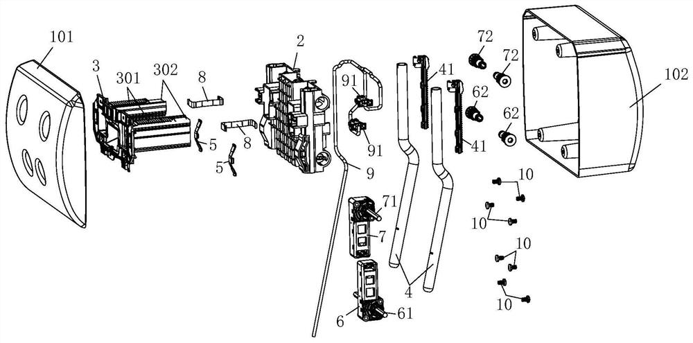
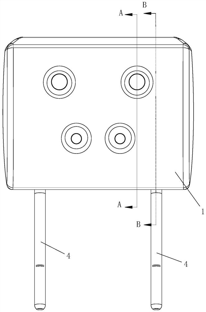
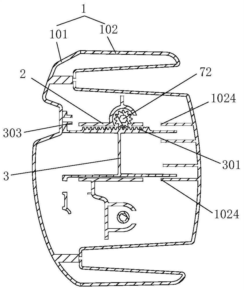
[0052] This embodiment relates to a seat headrest assembly. In terms of overall composition, the seat headrest assembly includes a headrest rod 4 , an intermediate bracket 2 , a sliding bracket 3 and a housing 1 .

[0053] Wherein, one end of the headrest rod 4 can be slidably arranged in the middle bracket 2 up and down, and the sliding bracket 3 can be slidably arranged in the middle bracket 2 back and forth. , and the front and rear driving parts connected with the sliding bracket 3 transmissions, the up and down driving parts are used to drive the middle bracket 2 to slide up and down along the headrest rod 4, and the front and rear driving parts are used to drive the sliding bracket 3 to slide back and forth relative to the middle bracket 2. In addition, the housing 1 is fixedly connected with the sliding bracket 3 , the intermediate bracket 2 and the sliding bracket 3 are accommodated in the housing 1 , and the other end of the headrest rod 4 protrudes out of the housing ...

Embodiment 2

[0085] This embodiment relates to a vehicle, and the seat of the vehicle is provided with the seat headrest assembly described in the first embodiment. Meanwhile, as a further preferred implementation form, the vehicle of this embodiment is further provided with a collision detection unit and a control unit. Among them, the collision detection unit is used to obtain the collision signal of the vehicle, and send the collision signal to the control unit, and the control unit is used to control the front and rear driving parts to make the seat headrest assembly close to the driver's head.

[0086] It should be noted that the collision detection unit in this embodiment may specifically use a radar, or other sensing components capable of checking an impending collision of a vehicle. However, the control unit in this embodiment can be an electronic control unit in a vehicle, that is, an ECU (Electronic Control Unit). The vehicle of this embodiment adopts the seat headrest assembly ...


PUM


Abstract

The invention provides a seat headrest assembly and a vehicle. The seat headrest assembly comprises a headrest rod, a middle support, a sliding support and a shell, and one end of the headrest rod is arranged in the middle support in an up-down sliding mode; the sliding support is arranged in the middle support in a front-back sliding mode. An up-down driving part and a front-back driving part are arranged on the middle bracket; the up-down driving part is in transmission connection with the headrest rod and is used for driving the middle bracket to slide up and down along the headrest rod; the front-back driving part is in transmission connection with the sliding bracket for driving the sliding bracket to slide back and forth relative to the middle bracket; the shell is fixedly connected with the sliding support, the middle support and the sliding support are contained in the shell, and the other end of the headrest rod extends out of the shell. According to the seat headrest assembly, four-direction adjustment of the headrest can be achieved, different position requirements of a user are met, and the using comfort of the headrest can be improved.

Description

technical field [0001] The invention relates to the technical field of seats, in particular to a seat headrest assembly. The present invention also relates to a vehicle having the above-mentioned seat headrest assembly. Background technique [0002] The headrest is an important personal protection component in the car, which plays a role in protecting the neck and head and relieving fatigue. When a vehicle collides with the rear, the human body will fall backward due to inertia. At this time, the pressure of vehicle acceleration or deceleration is concentrated on the fragile neck and head of the human body, and the headrest acts as a buffer to protect the human body's neck and head. head. [0003] At present, headrests are mainly divided into two categories, one is non-adjustable and the other is adjustable. Adjustable car headrests are further divided into manual adjustable and automatic adjustable. Among them, the manual adjustable type can only be adjusted in one dire...

Claims


Application Information

Patent Timeline
Patent Type & Authority Applications(China)
IPC IPC(8): B60N2/829B60N2/853
CPCB60N2/829B60N2/853
Inventor 熊丁罗鳌曾伟明张江林范业帝庞禄刘江芬
Owner 诺创汽车科技(上海)有限公司
Why Eureka
Try Eureka