
Steering column regulating device and electrical control steering column component

A steering column and adjustment device technology, applied in steering control, steering mechanism, vehicle components, etc., can solve the problems such as difficulty in accurately controlling the adjustment angle of the steering wheel, the amount of expansion and contraction, the inability to realize the memory function of the steering wheel position, and poor operating comfort. Achieve good practicability, simple structure, and reduce the overall cost

Inactive Publication Date: 2013-07-24
GREAT WALL MOTOR CO LTD
View PDF6 Cites 0 Cited by
  • Summary
  • Abstract
  • Description
  • Claims
  • Application Information

AI Technical Summary

Problems solved by technology

[0004] One is the mechanical four-way adjustment steering column, which is realized by mechanical locking and manual adjustment by the driver. The cost is relatively low, but this technology has poor operating comfort, and it is difficult to accurately control the angle and expansion of the steering wheel adjustment, and it is impossible to realize the adjustment of the steering wheel. location memory
[0005] The other is the electric four-way adjustment steering column. The electric motor integrated on the steering column drives the column tilting and telescopic mechanism to realize the tilting and telescopic four-way adjustment of the steering column. This technology can realize the four-way precision of the steering wheel. However, the existing electric four-way adjustment steering column adopts two electric motors to respectively drive the tilting and telescopic mechanism of the steering column to realize the four-way adjustment of the steering wheel. Since two electric motors and two sets of force transmission mechanisms are used, the The organization is more complicated and the cost is greatly increased

Method used


Image

  • Steering column regulating device and electrical control steering column component
  • Steering column regulating device and electrical control steering column component
  • Steering column regulating device and electrical control steering column component

Examples


Embodiment Construction

[0027] Embodiments of the present invention are described in detail below, examples of which are shown in the drawings, wherein the same or similar reference numerals designate the same or similar elements or elements having the same or similar functions throughout. The embodiments described below by referring to the figures are exemplary and are intended to explain the present invention and should not be construed as limiting the present invention.

[0028] In describing the present invention, it should be understood that the terms "center", "longitudinal", "transverse", "length", "width", "thickness", "upper", "lower", "front", " Orientation or position indicated by "back", "left", "right", "vertical", "horizontal", "top", "bottom", "inner", "outer", "clockwise", "counterclockwise", etc. The relationship is based on the orientation or positional relationship shown in the drawings, and is only for the convenience of describing the present invention and simplifying the descrip...


PUM


Abstract

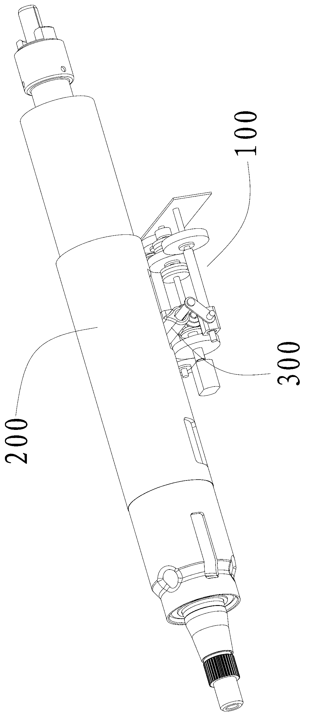
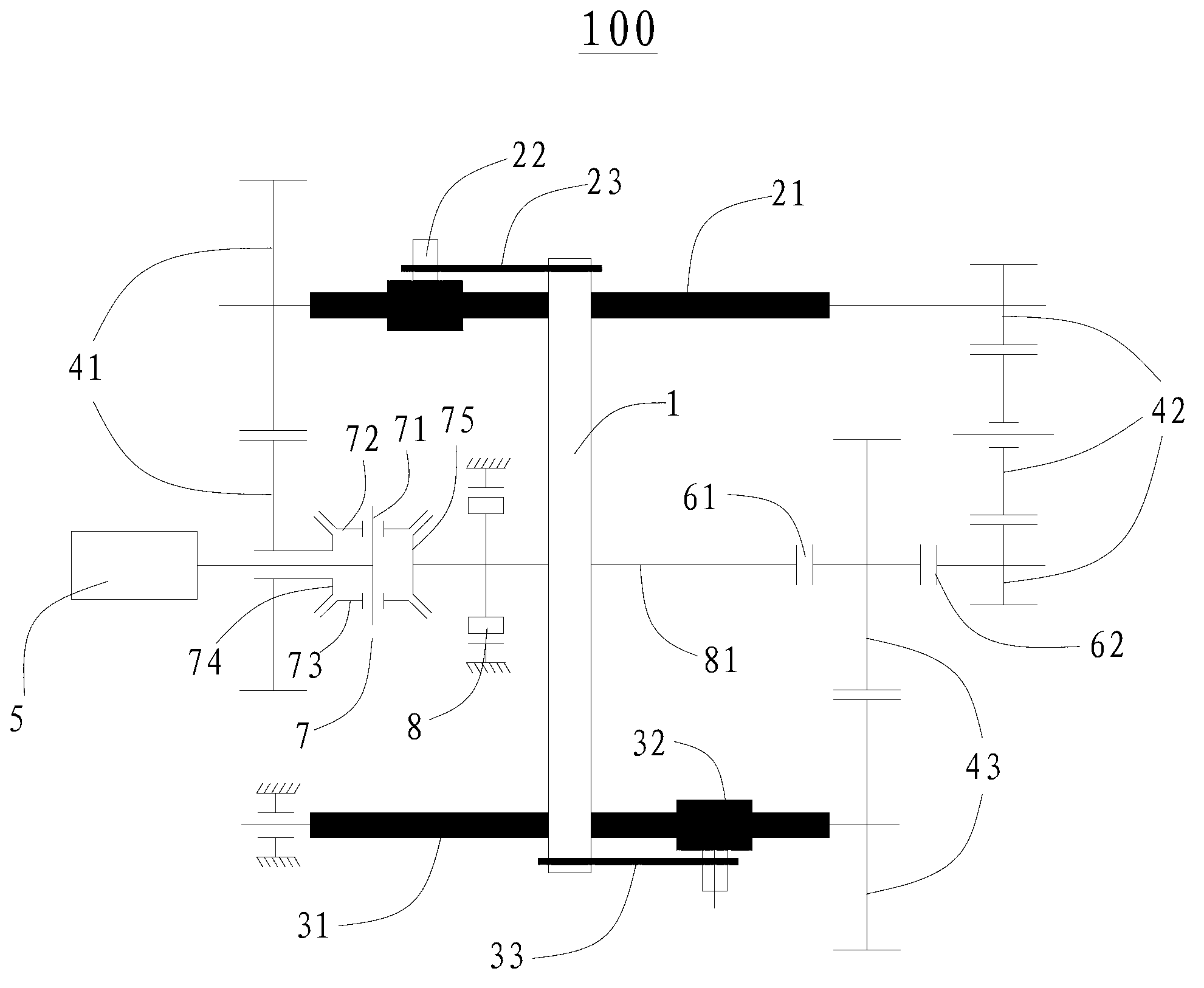
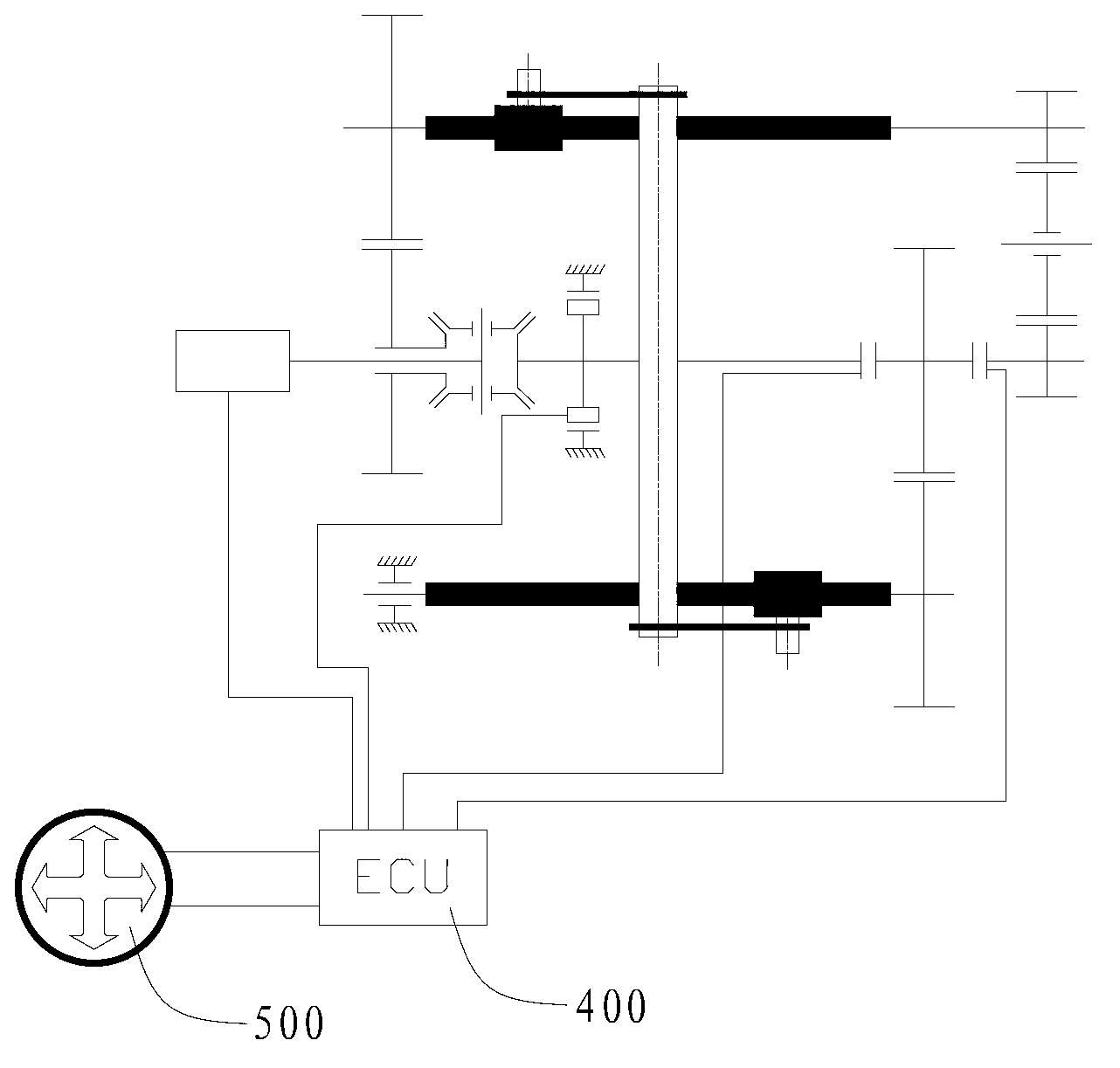
The invention discloses a steering column regulating device and an electrical control steering column component. The steering column regulating device comprises a steering column driving rod, a first lead screw, a second lead screw, a first screw, a second screw, a first connecting rod, a second connecting rod, a first output gear set, a second output gear set, a third output gear set, a driver, a first clutch and a second clutch, wherein the first screw is matched with the first lead screw, and the second screw is matched with the second lead screw. Two ends of the first connecting rod are respectively connected with the first screw and one end of the steering column driving rod in a rotatable mode. Two ends of the second connecting rod are respectively connected with the second lead screw and the other end of the steering column driving rod in a rotatable mode. The first output gear set is connected between the driver and the first lead screw. The third output gear set is connected between the second lead screw and the driver. The second output gear set is respectively connected with the first lead screw and the third output gear set. According to the steering column regulating device, four-directional regulation of a steering column be achieved only through one driver like a motor, structure is simple, and cost is low.

Description

technical field [0001] The invention relates to the technical field of automobile construction, in particular to a steering column adjustment device and an electronically controlled steering column assembly. Background technique [0002] With the continuous improvement of people's requirements for car handling comfort and driving feeling, the world's major car manufacturers continue to invest a lot of research and innovation in functional configuration and car handling. Among them, the steering wheel is one of the most frequently contacted and used auto parts by drivers, and the steering system is one of the most used systems by drivers. The position of the steering wheel relative to the driver's seat determines the driver's driving posture, and whether its position is appropriate determines the driver's driving comfort. Since the height and weight of the vehicle drivers are inconsistent, in order to take care of different consumers as much as possible, it is necessary to a...

Claims


Application Information

Patent Timeline
IPC IPC(8): B62D1/187B62D1/181
Inventor 黄勇李明
Owner GREAT WALL MOTOR CO LTD
Learn More