Method for automatically generating system object graph based on code analysis

A system object and automatic generation technology, applied in code compilation, program code conversion, creation/generation of source code, etc., can solve problems such as unable to automatically generate uml diagrams, redundant diagram information, etc., to enhance readability and maintainability sexual effect

Active Publication Date: 2018-11-06
FUZHOU UNIV
View PDF12 Cites 5 Cited by
  • Summary
  • Abstract
  • Description
  • Claims
  • Application Information

AI Technical Summary

Problems solved by technology

The problem with these UML generation tools is that when uml class and sequence diagrams are reversed in cod

Method used


Image

  • Method for automatically generating system object graph based on code analysis
  • Method for automatically generating system object graph based on code analysis
  • Method for automatically generating system object graph based on code analysis

Examples


Embodiment Construction

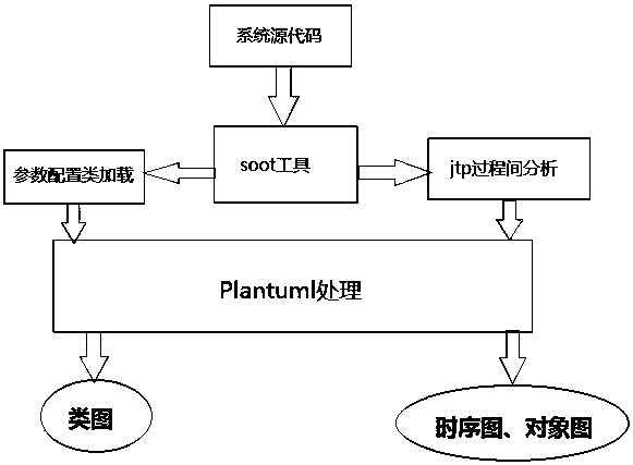
[0027] The present invention will be further explained below in conjunction with the drawings and specific embodiments.

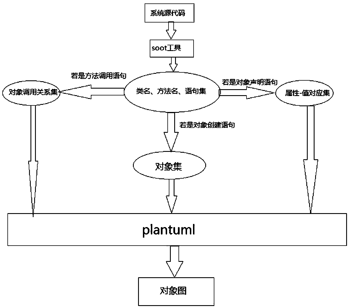
[0028] A method for automatically generating system object graphs based on code analysis includes the following steps: Step S1: Obtain class names, method names, and sentence sets through soot analysis; where the class set is C={C 0 ,C 1 ,C 2 ,...C i }Where C i Represents the class name: the collection of methods is M i ={M i0 ,M i1 ,M i2 ,...M ij }Where M ij Means C i The j-th method; the set of statements is U ij ={U ij0 ,U ij1 ,U ij2 …U ijk }Where U ijk Means M ij The kth statement of; the set of objects is OBJ = {obj 0 ,obj 1 ,obj 2 ,...Obj i }Where obj i Represents the i-th object Step S2: Process the object creation statement and generate an object set, process the object declaration statement and generate the attribute-value correspondence set, use the idea of ​​symbolic execution to obtain the method call statement and the calling process and generat...


PUM


Abstract

The invention provides a method for automatically generating a system object graph based on code analysis, which is characterized by comprising the following steps: step S1: obtaining a class name, amethod name and a statement set through soot analysis; step S2: processing an object creation statement and generating an object set, processing an object declaration statement and generating an attribute-value corresponding set, using a symbol executed idea to acquire a method calling statement and the calling process and generating an object calling relationship set; step S3: using a plantuml language rule to convert the aforementioned set into an object graph generating statement, thereby obtaining an automatically generated uml object graph. The system object graph automatic generation technology based on code analysis in the invention can directly reflect the characteristics of the runtime software architecture; the user can obtain object information (class attribute, object attribute) and object relationship (object call chain) by using the technology without having to view the cumbersome code, thereby enhancing the readability and maintainability of the code.

Description

Technical field [0001] The invention relates to a method for automatically generating system object graphs based on code analysis. Background technique [0002] In recent years, object-oriented software development technology has developed rapidly and has been widely used. It has obtained rich research results in object-oriented analysis, design technology and object-oriented programming language, and object-oriented methods occupy a dominant position. The unified modeling language UML is a universal and unified graphical modeling language in object-oriented software development, and is an effective tool for software system specification, visualization, and modeling. Therefore, in software engineering, engineers usually use uml design methods (ie, class diagrams, sequence diagrams, object diagrams) for detailed system design, so as to perform code writing and software development according to the detailed design, and generate code through uml diagrams. This belongs to Forward en...

Claims


Application Information

Patent Timeline
IPC IPC(8): G06F8/34G06F8/41
CPCG06F8/34G06F8/42
Inventor 陈星陈佳晴陈世鸿刘碧春朱芳宁
Owner FUZHOU UNIV
Why Eureka
Try Eureka