Method and device for determining positions of pixels on VR display screen in camera image

A camera imaging and display technology, which is applied in image communication, television, electrical components, etc., to achieve the effect of improving the determination accuracy

Active Publication Date: 2018-11-06
GOERTEK OPTICAL TECH CO LTD
8 Cites 4 Cited by

AI-Extracted Technical Summary

Problems solved by technology

[0003] There is a large error in the corresponding relationship between camera im...

Abstract

The invention discloses a method and a device for determining positions of pixels on a VR display screen in a camera image, comprising: acquiring an image obtained by a camera capturing a pattern displayed on the VR display screen through a VR lens, wherein the pattern is formed by the VR display screen lighting the pixels at equal interval; determining the first position information of each bright pixel in the image and the second position information on the VR display, and establishing a correspondence between the first position information and the second position information; determining the third position information of each dark pixel point in the image in the area surrounded by each four closely adjacent bright pixel points; selecting any three bright pixel points based on each area,and determining first position information and second position information respectively corresponding to the three bright pixels by using the correspondence; and determining fourth position information of the dark pixels in the VR display screen according to the third position information of the dark pixels, and the first position information and the second position information corresponding to each of the three bright pixels.

Application Domain

Technology Topic

Camera image

Image

  • Method and device for determining positions of pixels on VR display screen in camera image
  • Method and device for determining positions of pixels on VR display screen in camera image
  • Method and device for determining positions of pixels on VR display screen in camera image

Examples

  • Experimental program(1)

Example Embodiment

[0051] Various exemplary embodiments of the present invention will now be described in detail with reference to the accompanying drawings. It should be noted that the relative arrangement of components and steps, the numerical expressions and numerical values ​​set forth in these embodiments do not limit the scope of the invention unless specifically stated otherwise.
[0052] The following description of at least one exemplary embodiment is merely illustrative in nature and is in no way intended to limit the invention, its application, or uses.
[0053] Techniques, methods, and apparatus known to those of ordinary skill in the relevant art may not be discussed in detail, but where appropriate, such techniques, methods, and apparatus should be considered part of the specification.
[0054] In all examples shown and discussed herein, any specific values ​​should be construed as illustrative only and not limiting. Accordingly, other instances of the exemplary embodiment may have different values.
[0055] It should be noted that like numerals and letters refer to like items in the following figures, so once an item is defined in one figure, it does not require further discussion in subsequent figures.
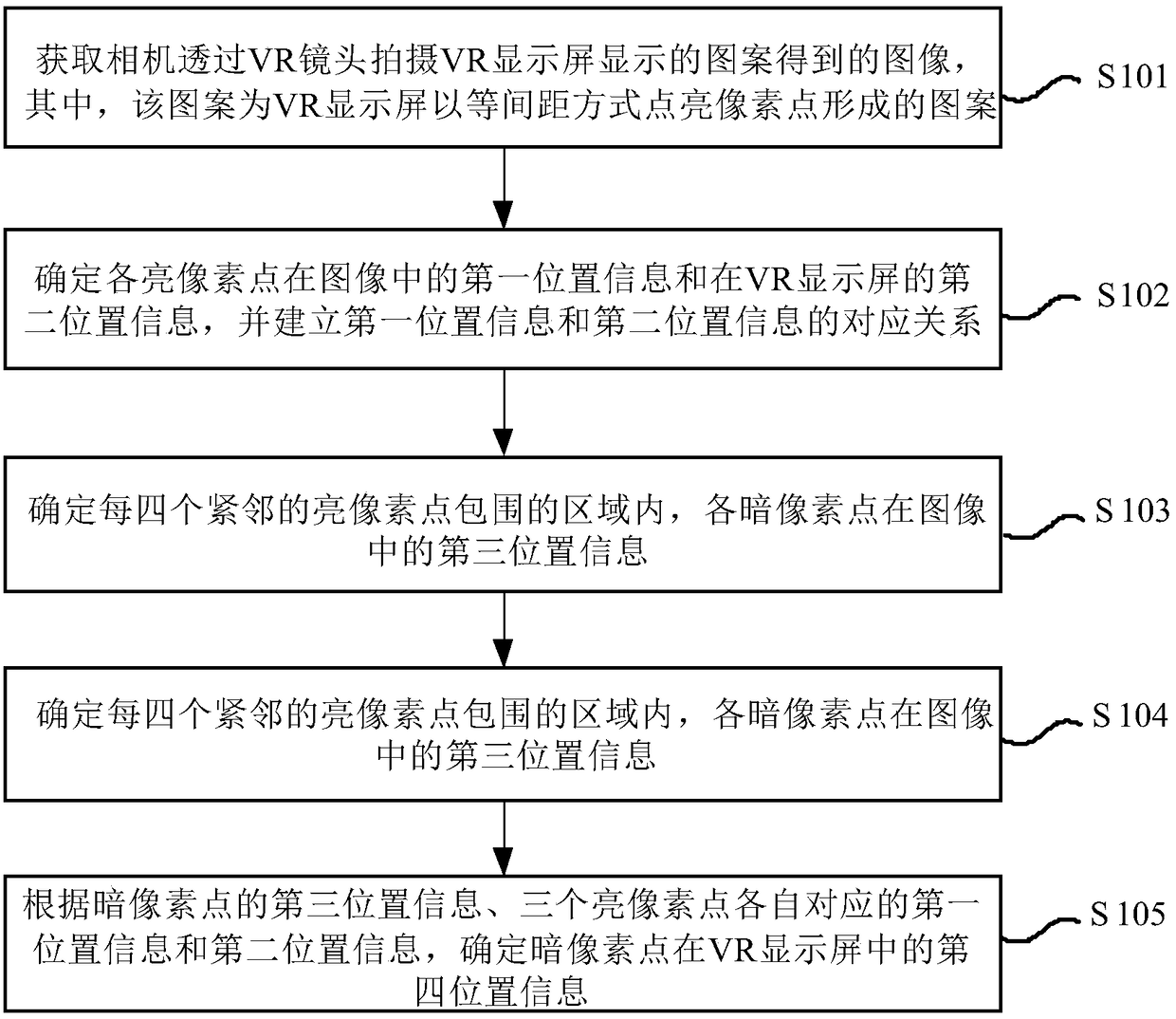
[0056] An embodiment of the present invention provides a method for determining the position of a pixel point on a VR display screen in camera imaging. figure 1 This is a process flow chart of a method for determining the position of a pixel point on a VR display screen in camera imaging according to an embodiment of the present invention. see figure 1 , the method includes at least steps S101 to S105.
[0057] Step S101 , acquiring an image obtained by a camera shooting a pattern displayed on a VR display screen through a VR lens, where the pattern is a pattern formed by lighting up pixels on the VR display screen in an equidistant manner.
[0058] figure 2 It is a partial screenshot of a pattern displayed on a VR display screen according to an embodiment of the present invention. see figure 2 , the distance between the lit pixel and each of its adjacent bright pixels is equal. The spacing can be any number of pixels. For example, the spacing is 10 pixels.
[0059] The display color of the lit pixel can be any one of red, green, and blue. When the lit pixel is displayed in red, the RGB value of the pixel is (255,0,0). When the lit pixel is displayed in green, the RGB value of the pixel is (0,255,0). When the lit pixel is displayed in blue, the RGB value of the pixel is (0,0,255).
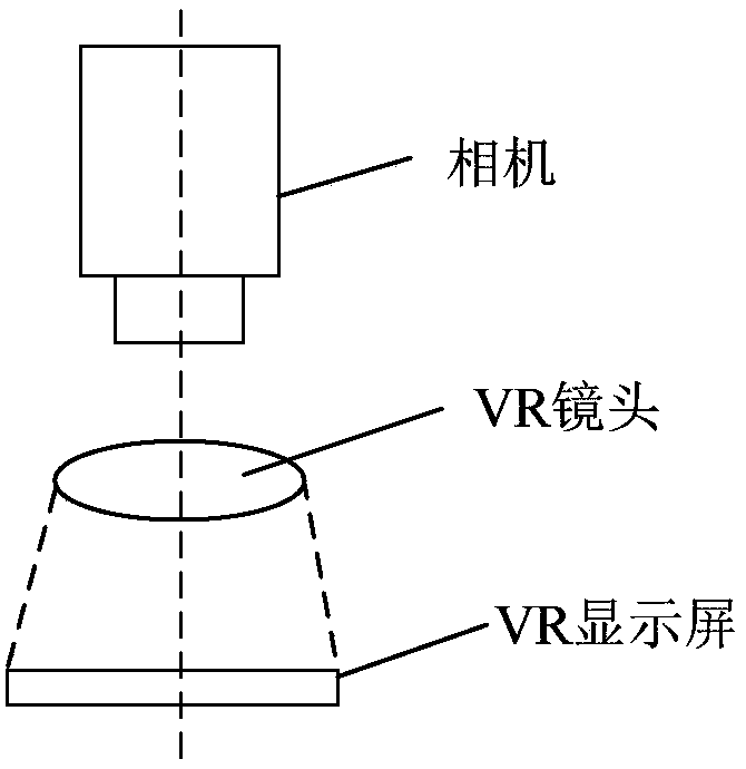
[0060] image 3 It is a schematic diagram of the positions of a camera and a VR device according to an embodiment of the present invention. see image 3 , the VR device only shows the VR lens and the VR display. The ideal positional relationship between the camera and the VR device is that when the camera is shooting, the optical axis of the camera is completely coincident with the optical axis of the VR lens. But this situation is difficult to satisfy.
[0061] In the embodiment of the present invention, when the camera is shooting, the optical axis of the camera and the optical axis of the VR lens meet the following requirements: when there is an included angle between the optical axis of the camera and the optical axis of the VR lens, the optical axis of the camera and the VR lens The included angle of the optical axis of the lens is within the preset angle range; when there is translation deviation between the optical axis of the camera and the optical axis of the VR lens, the translation deviation between the optical axis of the camera and the optical axis of the VR lens is within the preset deviation range .
[0062] The camera involved in the embodiment of the present invention may be an industrial camera.
[0063] The VR lens involved in the embodiment of the present invention may be a fisheye lens, and may also be any other type of lens.
[0064] Step S102: Determine the first position information of each bright pixel in the image and the second position information on the VR display screen, and establish a corresponding relationship between the first position information and the second position information.
[0065] In an embodiment of the present invention, the two-dimensional coordinate system established in the image is a coordinate system established with the horizontal direction of the image as the x-axis direction and the vertical direction of the image as the y-axis direction. The first position information of each bright pixel in the image is the coordinate value of the two-dimensional coordinate system established by each bright pixel in the image. A two-dimensional coordinate system is established on the VR display screen. The two-dimensional coordinate system is a coordinate system established with the horizontal direction of the VR display screen as the x-axis direction and the vertical direction of the VR display screen as the y-axis direction. The second position information of each bright pixel on the VR display screen is the coordinate value of the two-dimensional coordinate system established by each bright pixel on the VR display screen.
[0066] Due to the magnification of the VR lens, multiple pixels in the image captured by the camera represent one pixel on the VR display. In order to accurately determine the first position information of each bright pixel in the image, in the embodiment of the present invention, first, based on each bright pixel, determine the identification area surrounding the bright pixel, and then determine each pixel in the identification area. The gray value of the point, from the gray value of each pixel in the recognition area, select the pixel with the largest gray value, and use the position information of the pixel with the largest gray value in the image as the bright pixel in the image. first position information in the image. The size of the identification area can be determined according to the specific test situation.
[0067] Taking an area with a recognition area of ​​3*3 as an example, the recognition area includes 9 pixels. The grayscale values ​​of the nine pixels are 81, 144, 112, 77, 165, 115, 36, 83, and 46, respectively. The pixel with the largest gray value is the pixel corresponding to 165. The position information of the pixel corresponding to the gray value of 165 in the image is determined, and the position information is used as the first position information of the bright pixel surrounded by the identification area in the image.
[0068] In an embodiment of the present invention, first, the bright pixels in the image are sorted, the number of rows and columns where the bright pixels are located in all the bright pixels is determined, and the number of rows and columns displayed by the VR display screen is determined. The bright pixels are sorted, and the number of rows and columns where each bright pixel is located among all the bright pixels is determined. Then, establish a corresponding relationship between the first position information of the bright pixels in the image with the same number of rows and columns and the second position information of the bright pixels displayed on the VR display screen.
[0069] Figure 4 It is a partial screenshot of a pattern displayed on a VR display screen according to an embodiment of the present invention.
[0070] Figure 5 This is a partial schematic of the image of the pattern displayed on the VR display screen captured by the camera. by Figure 4 and
[0071] Figure 5 The illustrated part of the schematic diagram is taken as an example to describe establishing a corresponding relationship between the first location information and the second location information. lie in Figure 4 The position information of the bright pixel in the upper left corner on the VR display is (x 2 , y 2 ). lie in Figure 4 The bright pixels in the upper left corner are sorted at row 71 and column 194. lie in Figure 5 The position information of the bright pixel in the upper left corner in the image captured by the camera is (x 1 , y 1 ). lie in Figure 5 The bright pixels in the upper left corner are sorted at row 71 and column 194. lie in Figure 4 The bright pixels in the upper left corner and Figure 5 The bright pixel in the upper left corner has the same number of rows and columns and will be located in Figure 4 The location information and location of the bright pixel in the upper left corner on the VR display Figure 5 The position information of the bright pixel in the upper left corner in the image captured by the camera establishes a corresponding relationship. The content of the corresponding relationship includes the number of rows and columns where the bright pixels are located, the first position information and the second position information of the bright pixels.
[0072] Step S103 , determining the third position information of each dark pixel in the image in the area surrounded by every four adjacent bright pixels.
[0073] The third position information of each dark pixel in the image is the coordinate value of the two-dimensional coordinate system established by each dark pixel in the image.
[0074] Step S104, based on each area, select any three bright pixels, and use the corresponding relationship to determine the first position information and the second position information corresponding to each of the three bright pixels.
[0075] In an embodiment of the present invention, first, the number of rows and columns where the three bright pixels are located in all the bright pixels in the image is determined. Then, the first position information and the second position information corresponding to each of the three bright pixels are determined according to the number of rows, columns and correspondence of the three bright pixels in all the bright pixels in the image.
[0076] Image 6 This is a partial schematic of the image of the pattern displayed on the VR display screen captured by the camera. In this embodiment of the present invention, from Image 6 In the four adjacent bright pixels shown, the selected three bright pixels can be any combination of the following, bright pixel 1, bright pixel 2 and bright pixel 3, bright pixel 1, bright pixel 2 and bright pixel 4, bright pixel 1, bright pixel 3 and bright pixel 4, bright pixel 2, bright pixel 3 and bright pixel 4.
[0077] Step S105: Determine the fourth position information of the dark pixel in the VR display screen according to the third position information of the dark pixel, the first position information and the second position information corresponding to each of the three bright pixels.
[0078] The fourth position information of the dark pixel in the VR display screen is the coordinate value of the two-dimensional coordinate system established on the VR display screen.
[0079] Take the selected three bright pixels as Image 6 The bright pixel point 1, the bright pixel point 2 and the bright pixel point 3 are shown as an example, to determine the Image 6 The fourth position information of the shown dark pixel point a will be described. The first position information of bright pixel 1, bright pixel 2 and bright pixel 3 in the image captured by the camera is (x 1 , y 1 ), (x 2 , y 2 ), (x 3 , y 3 ). The second position information of bright pixel 1, bright pixel 2 and bright pixel 3 on the VR display screen is (x 1d , y 1d ), (x 2d , y 2d ), (x 3d , y 3d ). The third position information of the dark pixel point a in the image captured by the camera is (x, y). Based on the following formula, the fourth position information (x d , y d ),
[0080] x d =x 1d +(x 2d -x 1d )*[(x-x 1 )/(x 2 -x 1 )]—calculation formula (1),
[0081] y d =y 1d +(y 3d -y 1d )*[(y-y 1 )/(y 3 -y 1 )]—calculation (2).
[0082] Image 6 The dark pixels a and b in the Image 6 For the convenience of explanation, in fact, the dark pixel point a and the dark pixel point b are displayed as black.
[0083] Image 6 The dark pixel point b shown is located in the same row as the bright pixel point 1 and the bright pixel point 2. In this case, the above-mentioned calculation formula (1) and calculation formula (2) are also applicable.
[0084]For a dark pixel located at the edge of the camera image, since the number of bright pixels surrounding the dark pixel is less than three, the bright pixels surrounding the dark pixel are supplemented by three. For example, in the image captured by the camera, the third bright pixel to be supplemented is determined according to the two bright pixels next to the dark pixel, and the position information of the third bright pixel to be supplemented in the image is determined , and, according to the two bright pixels adjacent to the dark pixel, determine the third bright pixel to be supplemented, and determine the position information of the third bright pixel to be supplemented on the VR display screen. Then, the above-mentioned calculation formula (1) and calculation formula (2) are used to determine the fourth position information of the dark pixel point. When the third bright pixel is added to the image captured by the camera, the third bright pixel can be located in the same row or the same column as any one of the known two bright pixels, so that the three bright pixels The area enclosed by the dots can surround the dark pixels. At the same time, the distance between the third bright pixel point and the known bright pixel points located in the same row or the same column is equal to the distance between the known two bright pixel points. The third bright pixel is complemented on the VR display in the same way as the third bright pixel is complemented in the image captured by the camera.
[0085] The method for determining the position of the pixel point on the VR display screen in the camera imaging provided by the embodiment of the present invention improves the accuracy of determining the position of the pixel point in the VR display screen in the camera imaging, and the accuracy can be within one pixel.
[0086] The method for determining the position of a pixel point on the VR display screen in camera imaging provided by the embodiment of the present invention can be used to determine the size of the display area of ​​the VR display screen.
[0087] Based on the same inventive concept, an embodiment of the present invention provides a device for determining the position of a pixel in a camera imaging on a VR display screen. Figure 7 It is a schematic structural diagram of an apparatus for determining the position of a pixel point on a VR display screen in camera imaging according to an embodiment of the present invention. see Figure 7 , the device includes at least: an acquisition module 710 for acquiring an image obtained by a camera shooting a pattern displayed on a VR display screen through a VR lens, wherein the pattern is a pattern formed by lighting up pixels on the VR display screen in an equidistant manner; the corresponding relationship The establishment module 720 is used to determine the first position information of each bright pixel in the image and the second position information in the VR display screen, and establish the corresponding relationship between the first position information and the second position information; the first determination module 730 , used to determine the third position information of each dark pixel in the image in the area surrounded by every four immediately adjacent bright pixels; the second determination module 740 is used to select any three bright pixels based on each area point, and use the corresponding relationship to determine the first position information and the second position information corresponding to each of the three bright pixels; the third determination module 750 is used for the third position information of the dark pixels and the three bright pixels according to the third position information. The corresponding first position information and the second position information determine the fourth position information of the dark pixel in the VR display screen.
[0088] In one embodiment of the present invention, the corresponding relationship establishing module 720 is further configured to: determine the identification area surrounding the bright pixel based on each bright pixel; determine the gray value of each pixel in the identification area; select the gray value The largest pixel point, and the position information of the pixel point with the largest gray value in the image is taken as the first position information of the bright pixel point in the image.
[0089] In one embodiment of the present invention, the correspondence establishing module 720 is further configured to: sort the bright pixels in the image, determine the number of rows and columns where the bright pixels are located in all the bright pixels, and, Sort the bright pixels displayed on the VR display screen, and determine the number of rows and columns where each bright pixel is located among all the bright pixels; A corresponding relationship is established between the first position information and the second position information of the bright pixels displayed on the VR display screen.
[0090] In an embodiment of the present invention, the second determining module 740 is further configured to: determine the number of rows and columns where the three bright pixels are located in all the bright pixels in the image; The number of rows, columns and the corresponding relationship of the bright pixels in all the bright pixels in the image determine the first position information and the second position information corresponding to each of the three bright pixels.
[0091] Figure 8 It is a schematic diagram of the hardware structure of a device for determining the position of a pixel point on a VR display screen in camera imaging according to an embodiment of the present invention. see Figure 8 , the device for determining the position of the pixel in the camera imaging on the VR display screen includes: a memory 820 and a processor 810 . The memory 820 is used for storing instructions, and the instructions are used to control the processor 810 to operate to execute the method for determining the position of a pixel in the camera imaging provided in any embodiment of the present invention on the VR display screen.
[0092] The host to which the present invention relates may be a system, method and/or computer program product. The computer program product may include a computer-readable storage medium having computer-readable program instructions loaded thereon for causing a processor to implement various aspects of the present invention.
[0093] A computer-readable storage medium may be a tangible device that can hold and store instructions for use by the instruction execution device. The computer-readable storage medium may be, for example, but not limited to, an electrical storage device, a magnetic storage device, an optical storage device, an electromagnetic storage device, a semiconductor storage device, or any suitable combination of the foregoing. More specific examples (non-exhaustive list) of computer readable storage media include: portable computer disks, hard disks, random access memory (RAM), read only memory (ROM), erasable programmable read only memory (EPROM) or flash memory), static random access memory (SRAM), portable compact disk read only memory (CD-ROM), digital versatile disk (DVD), memory sticks, floppy disks, mechanically coded devices, such as printers with instructions stored thereon Hole cards or raised structures in grooves, and any suitable combination of the above. Computer-readable storage media, as used herein, are not to be construed as transient signals per se, such as radio waves or other freely propagating electromagnetic waves, electromagnetic waves propagating through waveguides or other transmission media (eg, light pulses through fiber optic cables), or through electrical wires transmitted electrical signals.
[0094] The computer readable program instructions described herein may be downloaded to various computing/processing devices from a computer readable storage medium, or to an external computer or external storage device over a network such as the Internet, a local area network, a wide area network, and/or a wireless network. The network may include copper transmission cables, fiber optic transmission, wireless transmission, routers, firewalls, switches, gateway computers, and/or edge servers. A network adapter card or network interface in each computing/processing device receives computer-readable program instructions from a network and forwards the computer-readable program instructions for storage in a computer-readable storage medium in each computing/processing device .
[0095] The computer program instructions for carrying out the operations of the present invention may be assembly instructions, instruction set architecture (ISA) instructions, machine instructions, machine dependent instructions, microcode, firmware instructions, state setting data, or instructions in one or more programming languages. Source or object code written in any combination, programming languages ​​including object-oriented programming languages ​​- such as Smalltalk, C++, etc., and conventional procedural programming languages ​​- such as the "C" language or similar programming languages. The computer readable program instructions may execute entirely on the user's computer, partly on the user's computer, as a stand-alone software package, partly on the user's computer and partly on a remote computer, or entirely on the remote computer or server implement. In the case of a remote computer, the remote computer may be connected to the user's computer through any kind of network, including a local area network (LAN) or a wide area network (WAN), or may be connected to an external computer (eg, using an Internet service provider through the Internet connect). In some embodiments, custom electronic circuits, such as programmable logic circuits, field programmable gate arrays (FPGAs), or programmable logic arrays (PLAs), can be personalized by utilizing state information of computer readable program instructions. Computer readable program instructions are executed to implement various aspects of the present invention.
[0096] Aspects of the present invention are described herein with reference to flowchart illustrations and/or block diagrams of methods, apparatus (systems) and computer program products according to embodiments of the invention. It will be understood that each block of the flowchart illustrations and/or block diagrams, and combinations of blocks in the flowchart illustrations and/or block diagrams, can be implemented by computer readable program instructions.
[0097] These computer readable program instructions may be provided to a processor of a general purpose computer, special purpose computer or other programmable data processing apparatus to produce a machine that causes the instructions when executed by the processor of the computer or other programmable data processing apparatus , resulting in means for implementing the functions/acts specified in one or more blocks of the flowchart and/or block diagrams. These computer readable program instructions can also be stored in a computer readable storage medium, these instructions cause a computer, programmable data processing apparatus and/or other equipment to operate in a specific manner, so that the computer readable medium on which the instructions are stored includes An article of manufacture comprising instructions for implementing various aspects of the functions/acts specified in one or more blocks of the flowchart and/or block diagrams.
[0098] Computer readable program instructions can also be loaded onto a computer, other programmable data processing apparatus, or other equipment to cause a series of operational steps to be performed on the computer, other programmable data processing apparatus, or other equipment to produce a computer-implemented process , thereby causing instructions executing on a computer, other programmable data processing apparatus, or other device to implement the functions/acts specified in one or more blocks of the flowcharts and/or block diagrams.
[0099] The flowchart and block diagrams in the Figures illustrate the architecture, functionality, and operation of possible implementations of systems, methods and computer program products according to various embodiments of the present invention. In this regard, each block in the flowchart or block diagrams may represent a module, segment, or portion of instructions, which comprises one or more executables for implementing the specified logical function(s) instruction. In some alternative implementations, the functions noted in the blocks may occur out of the order noted in the figures. For example, two blocks in succession may, in fact, be executed substantially concurrently, or the blocks may sometimes be executed in the reverse order, depending upon the functionality involved. It is also noted that each block of the block diagrams and/or flowchart illustrations, and combinations of blocks in the block diagrams and/or flowchart illustrations, can be implemented in dedicated hardware-based systems that perform the specified functions or actions , or can be implemented in a combination of dedicated hardware and computer instructions. It is well known to those skilled in the art that implementation in hardware, implementation in software, and implementation in a combination of software and hardware are all equivalent.
[0100] Various embodiments of the present invention have been described above, and the foregoing descriptions are exemplary, not exhaustive, and not limiting of the disclosed embodiments. Numerous modifications and variations will be apparent to those of ordinary skill in the art without departing from the scope and spirit of the described embodiments. The terminology used herein was chosen to best explain the principles of the embodiments, the practical application or technical improvement in the marketplace, or to enable others of ordinary skill in the art to understand the embodiments disclosed herein. The scope of the invention is defined by the appended claims.

PUM

no PUM

Description & Claims & Application Information

We can also present the details of the Description, Claims and Application information to help users get a comprehensive understanding of the technical details of the patent, such as background art, summary of invention, brief description of drawings, description of embodiments, and other original content. On the other hand, users can also determine the specific scope of protection of the technology through the list of claims; as well as understand the changes in the life cycle of the technology with the presentation of the patent timeline. Login to view more.

Similar technology patents

Emergency rescue intelligent lighting control system for 10KM-level ultra-long highway tunnel

PendingCN114364105AImprove the determination accuracyReduce traffic congestionControlling traffic signalsImage analysisLighting systemTraffic crash
Owner:CHONGQING JIAOTONG UNIVERSITY

Classification and recommendation of technical efficacy words

  • Improve the determination accuracy

Method for measuring low background carrier concentration by utilizing optical excitation differential capacitance method

ActiveCN102175727AEasy to judge and implementImprove the determination accuracyMaterial capacitanceScanning probe microscopyPhysicsDifferential capacitance
Owner:SHANGHAI INST OF TECHNICAL PHYSICS - CHINESE ACAD OF SCI

Altered volcano rock effective reservoir determination method ad device in oil-gas exploration

ActiveCN103616731AImprove the determination accuracyMeet production needsGeological measurementsCore StoragePositive correlation
Owner:PETROCHINA CO LTD
Why Eureka
Try Eureka