Step-down gear unit

A technology for reduction gears and transmission systems, applied in gear transmissions, belts/chains/gears, mechanical equipment, etc., can solve problems such as high manufacturing costs, achieve economical production measures, reduce friction, and achieve the effects of small and compact structures

Inactive Publication Date: 2002-07-17
IMS 传动装置有限公司
View PDF6 Cites 0 Cited by
  • Summary
  • Abstract
  • Description
  • Claims
  • Application Information

AI Technical Summary

Problems solved by technology

[0013] Since all the individual parts of these known mechanisms are made of steel or similar materials, the mechanisms are usually equipped with radially elastic, i.e. deformable ball bearings arranged in the center of an elliptical drive core. Between the circumferential surface and the flexible rolling bush, these mechanisms require considerable manufacturing effort, especially since high finishing precision is a prerequisite for trouble-free operation

Method used


Image

  • Step-down gear unit
  • Step-down gear unit
  • Step-down gear unit

Examples


Embodiment Construction

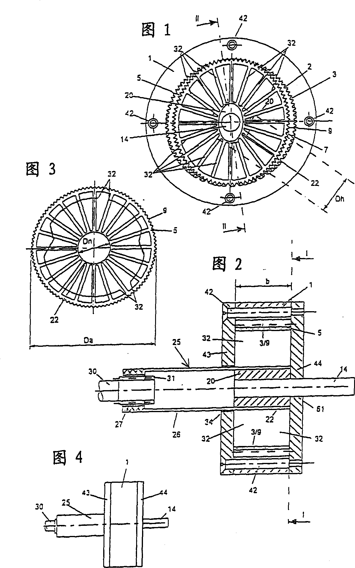
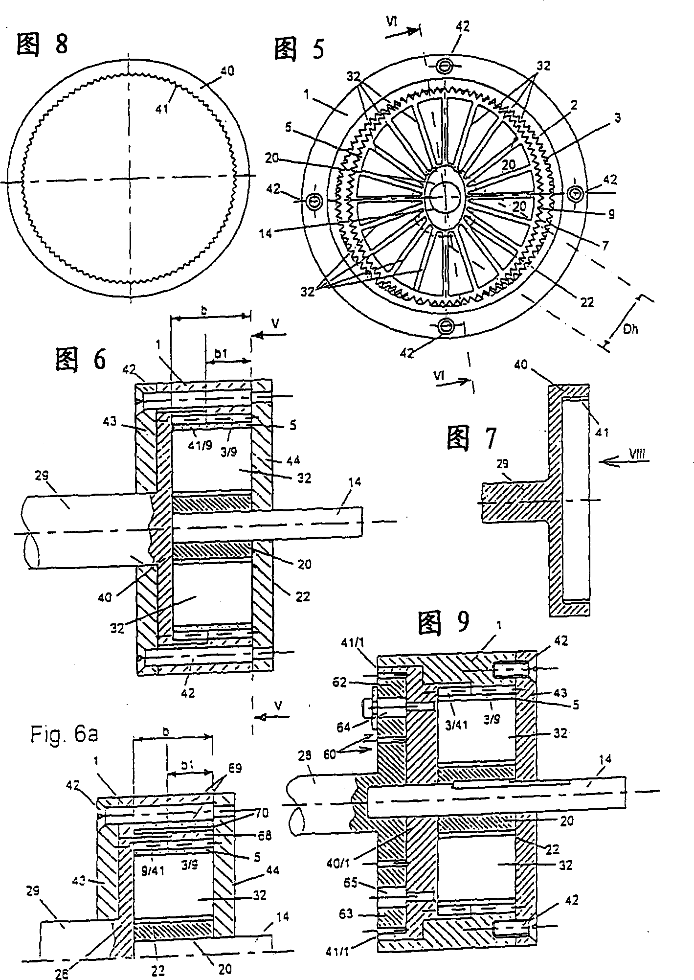
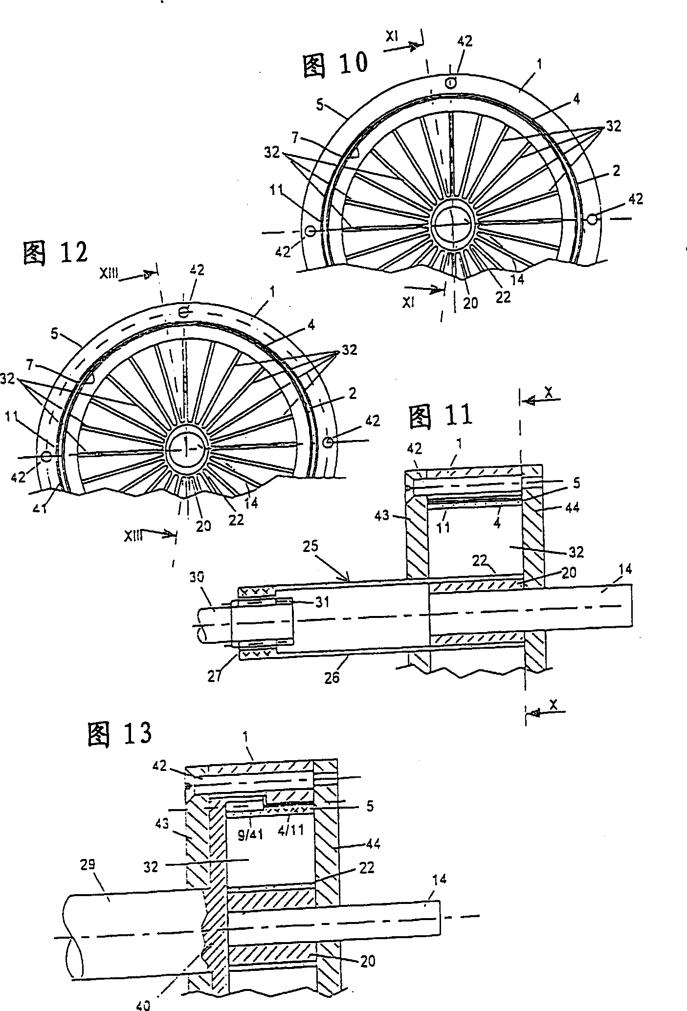
[0077] Various embodiments of the reduction gear system will be described below with reference to the figures presented above, the essential parts of which are in each case: a circular bearing ring 1 with a circular inner bearing surface 2, a circular bearing ring 1 with an outer peripheral surface 7 rolling sleeve 5, and an oval or triangular drive core 20 or 20 / 1.

[0078] In the exemplary embodiment of Figures 1, 2 and 3, the cylindrical support ring 1 is provided with internal teeth 3 which extend across its entire width b. As a fixed gear part, the above-mentioned support ring 1 is non-rotatably connected to any mechanism carrier not shown in the figures or the like. End walls 43 and 44 , which are connected to each other or to the support ring 1 with axial screws 42 , are respectively arranged on their two side faces. In the central opening 61 of the end wall 44 is mounted a drive shaft 14 for rotation, which is connected, for example, to a drive motor and designed to b...


PUM


Abstract

The invention concerns a step-down gear unit with a rigid support ring (1), comprising a substantially cylindrical support surface (1), and with a radially flexible rolling collet (5) which has an outer generated surface (7) with a smaller peripheral length than the support surface (2), one or a plurality of peripheral sections of the outer generated surface (7) being held in substantially slip-free engagement in continuous exchange with the support surface (2) of the support ring (1) by one or a plurality of parts lying on an enveloping circle of a drive core (20) which is rotatably disposed inside the rolling collet (5) and is rotated by a drive shaft (14). The enveloping circle (20) of the driven elliptical drive core (20) has a substantially smaller diameter (Dh) than the basically cylindrical rolling collet (5). The rolling collet (5) is supported on the drive core (20) by a plurality of substantially radial transmission elements (32) which are all of equal length.

Description

technical field [0001] The present invention relates to a reduction gear transmission system having the following features: a rigid bearing ring having a substantially cylindrical bearing surface, a radially deformable rolling sleeve having an outer periphery having a shorter circumferential length than the bearing surface To the surface, a drive shaft, a drive core whose cross-section is non-circular, which can be rotated by the drive shaft and forms an enveloping circle here, through the rotational movement of the non-circular drive core, the rolling sleeve At least one circumferential segment of the outer circumferential surface alternates in succession in substantially slip-free engagement with the bearing surface of the bearing ring. Background technique [0002] Such mechanisms are known in the technical field by the term "harmonic drive system" (Dubbel, Handbook of Mechanical Engineering, 15th edition, page 1069; Harmonic Drive Systems GmbH, 63225, Langen / Hessen, comp...

Claims


Application Information

Patent Timeline
Patent Type & Authority Patents(China)
IPC IPC(8): F16H1/32F16H49/00
CPCF16H49/001Y10T74/19F16H49/00
Inventor 赫尔穆特·伊恩弗朗斯·劳登巴赫
Owner IMS 传动装置有限公司
Why Eureka
Try Eureka