Supercharge Your Innovation With Domain-Expert AI Agents!

Efficient screening equipment

A screening material and high-efficiency technology, applied in the direction of screening, solid separation, grille, etc., can solve the problems of low efficiency, uneven sand screening machines, etc., and achieve the effect of good sand screening effect and high sand screening efficiency

Inactive Publication Date: 2018-11-13
SUZHOU HUICHENG PRECISION MOLD
View PDF0 Cites 0 Cited by
  • Summary
  • Abstract
  • Description
  • Claims
  • Application Information

AI Technical Summary

Problems solved by technology

[0002] Sand screening is an inevitable link in the civil construction process. Whether it is a supplier or a builder, sand materials must be processed. In the past, sand screening often used workers' time for manual processing. However, in the face of large projects, the efficiency is often low, and the market The sand screening machines on the market are good and bad. How to efficiently process raw sand is a concern of many suppliers and builders.

Method used


Image

  • Efficient screening equipment
  • Efficient screening equipment
  • Efficient screening equipment

Examples


Embodiment 1

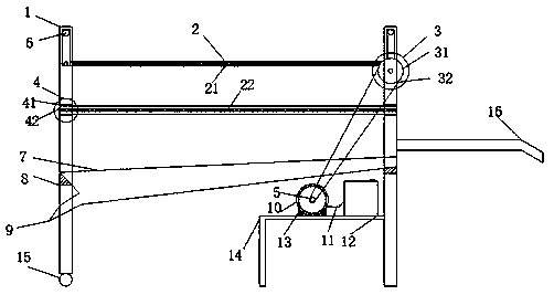
[0017] see figure 1 As shown, the movable rod 33 is rotationally connected with the frame leg 1 through the movable wheel 6, and the primary screen 21 is connected with the movable rod 33 through the rotating mechanism 3. The mesh distance of the primary screen is slightly larger, in order to allow more impurities The faster sieving of the former sand material, the rotating mechanism 3 includes a driven wheel 31, a belt 32, a movable rod 33 and a connecting shaft 34, and the rotating mechanism 3 is driven by the engine 10 to make the screen cloth do periodic motion. The secondary screen 22 is slidingly connected with the frame leg 1 through the inserting plate structure 4. The mesh distance of the secondary screen 22 is relatively small, and is used to block the finer impurities that are not filtered out by the primary screen 21, and pass through the inserting plate structure. Can be pulled out for cleaning. The sand-collecting funnel 7 is fixedly placed on the bridge 8 of th...

Embodiment 2

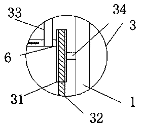
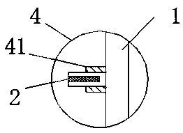
[0019] see Figure 2-3 As shown, the driven wheel 31 is fixedly connected to the frame leg 1 through the connecting shaft 34 , and the movable rod 33 is rotationally connected to the primary screen 21 through the movable wheel 6 . The driving wheel 5 is rotationally connected to the driven wheel 31 through a belt 32 . The engine 10 drives the driving wheel 5 to rotate, thereby driving the driven wheel 31, and the primary screen 21 moves periodically around the driven wheel 31 to realize preliminary filtration of raw sand. The flashboard structure 4 includes a support 41, and the secondary screen 22 is in a sliding connection with the support 41, and can be pulled out for cleaning when cleaning impurities on the secondary screen 22.

[0020] The building sand screening machine of the present invention adopts an automatic double filter design, pours the raw sand material into the primary screen 21, and is driven by the engine 10 to perform periodic motions to filter out larger ...


PUM


Abstract

The invention discloses efficient screening equipment which comprises rack legs and a screen. The efficient screening equipment has the beneficial effects that: when raw sand is poured onto the screen, a motor is started to drive a rotary mechanism for filtering the raw sand preliminarily, and re-filtering the raw sand on a sand screen below. The novel sand screening equipment is equipped with a sand collecting funnel, so that the screened sand is collected and guided out through the sand collecting funnel. The efficient screening equipment adopts an automatic sand screening design, and can save a great deal of labor power and time; dual sand screening design is adopted, so that the sand treated by the equipment is better in quality, and can be used for the building industry better. Duringdesign, a practical using condition is considered, a semi-fixed type structure is adopted, and the equipment can be moved to a working place through a foot wheel and a handle at one side, so that theefficient screening equipment is normally placed down in use; and the rack legs are arranged at the sides, so that the equipment can be fixed on ground very well, and therefore, stability is good.

Description

technical field [0001] The invention relates to civil construction, in particular to high-efficiency screening equipment, which belongs to the field of construction equipment. Background technique [0002] Sand screening is an inevitable link in the civil construction process. Whether it is a supplier or a builder, sand materials must be processed. In the past, sand screening often used workers' time for manual processing. However, in the face of large projects, the efficiency is often low. The market The sand screening machines on the market vary from good to bad. How to efficiently process raw sand is a concern of many suppliers and builders. Contents of the invention [0003] The purpose of the present invention is to realize efficient and reliable treatment of the problem of many impurities in the sand material. [0004] The present invention achieves the above purpose through the following technical solutions, including frame legs, screens, primary screens, secondary...

Claims


Application Information

Patent Timeline
IPC IPC(8): B07B1/28B07B1/42B07B1/46
CPCB07B1/28B07B1/42B07B1/46B07B2201/04
Inventor 顾超
Owner SUZHOU HUICHENG PRECISION MOLD
Features
  • R&D
  • Intellectual Property
  • Life Sciences
  • Materials
  • Tech Scout
  • Unparalleled Data Quality
  • Higher Quality Content
  • 60% Fewer Hallucinations
Learn More