Grooving device for installation of building monitoring equipment
A technology for monitoring equipment and installation, which is applied in the field of slotting devices for installation of building monitoring equipment, which can solve the problems that dust cannot be reduced and waste cannot be collected, and achieve good dust reduction effect and high work efficiency
- Summary
- Abstract
- Description
- Claims
- Application Information
AI Technical Summary
Problems solved by technology
Method used
Image

Examples
Embodiment 1
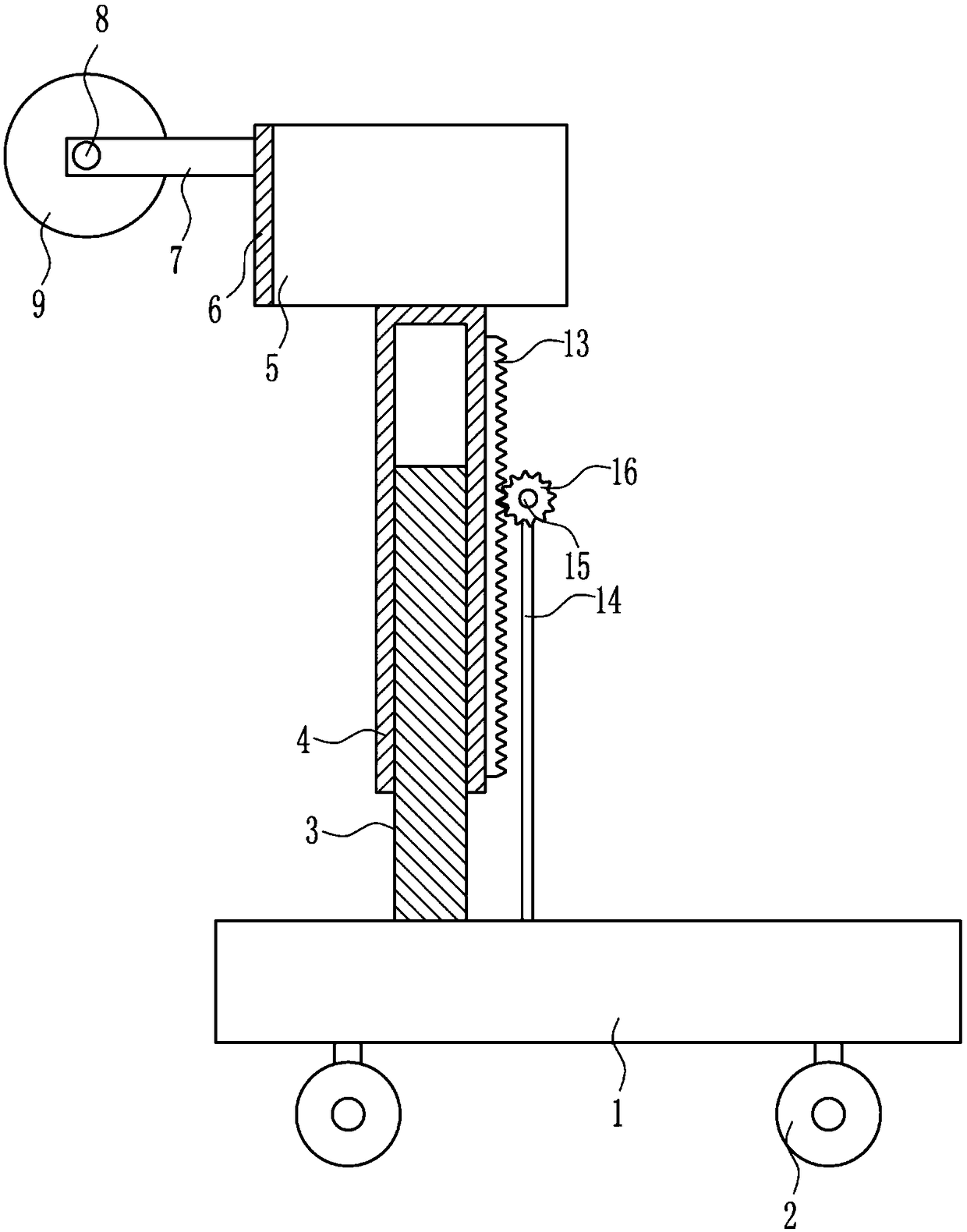
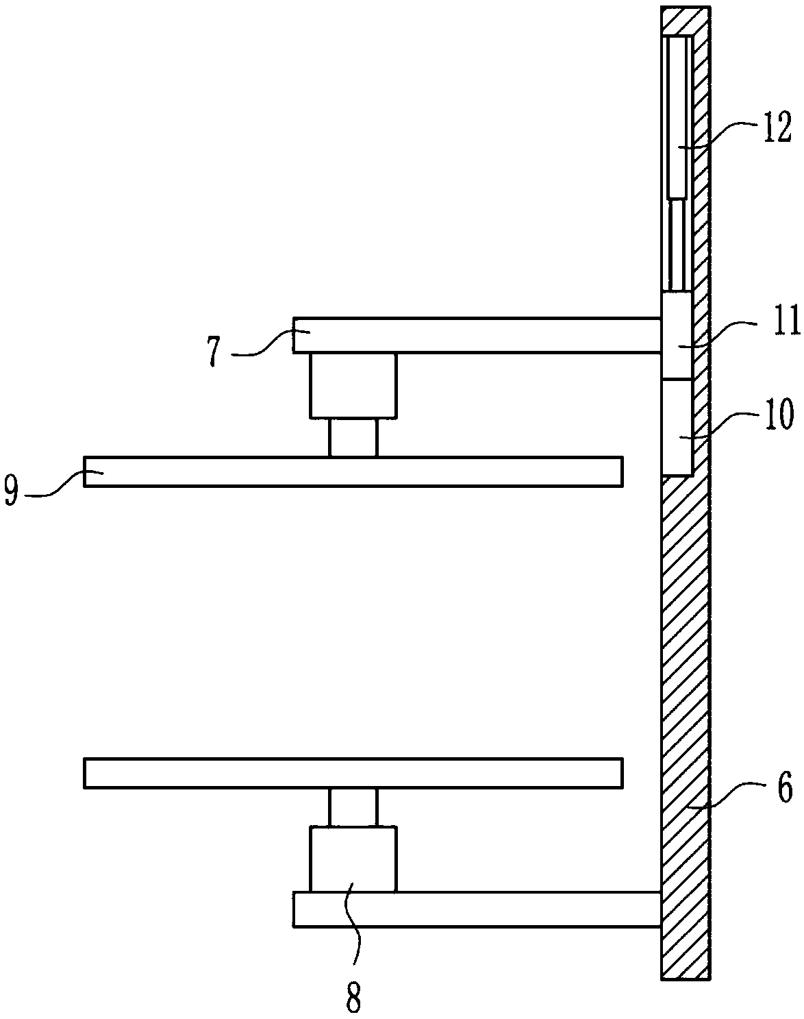
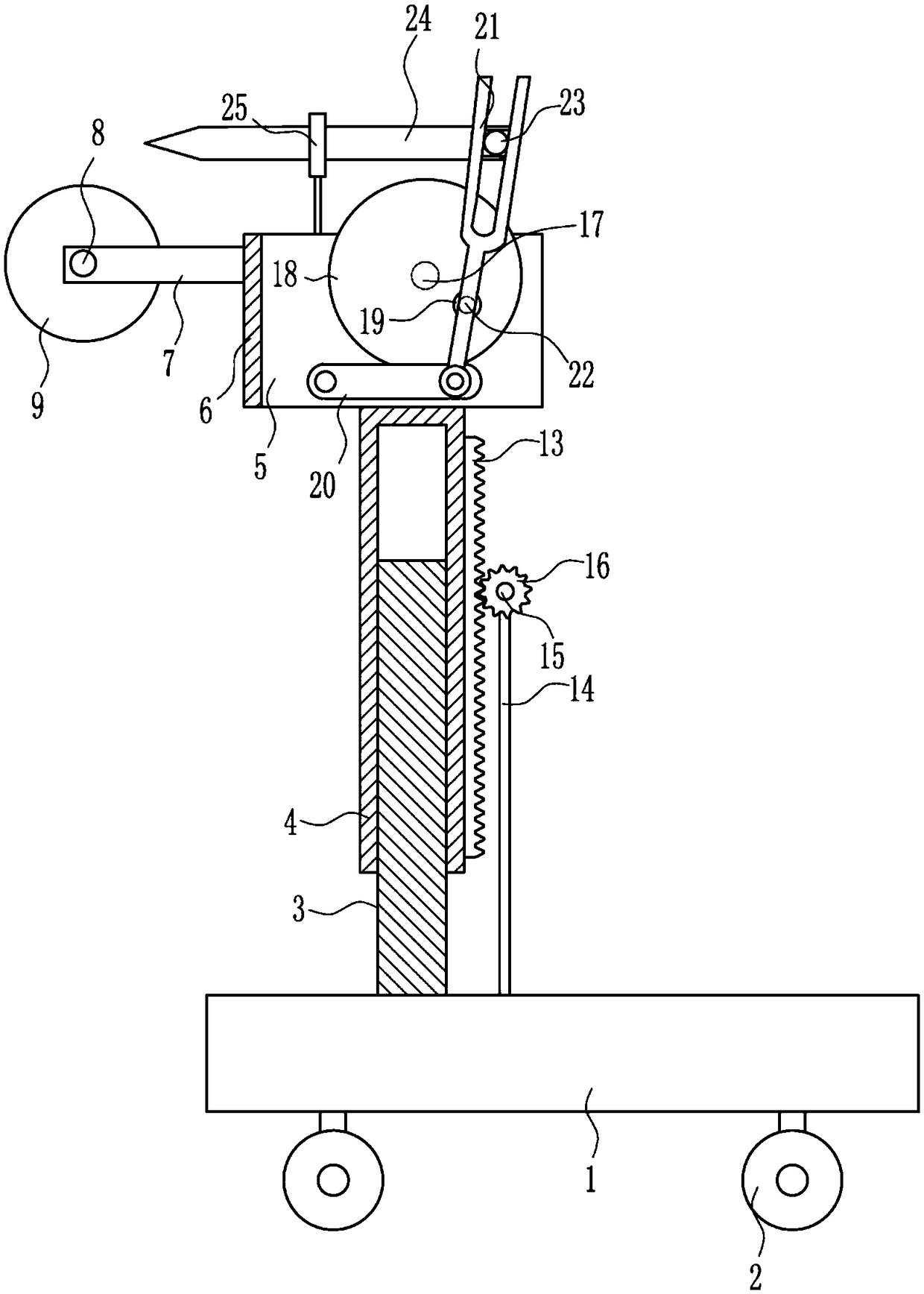
[0024] A slotting device for building monitoring equipment installation, such as Figure 1-4 As shown, it includes base 1, wheel 2, inner telescopic rod 3, outer telescopic rod 4, connecting block 5, connecting plate 6, connecting rod 7, first motor 8, saw blade 9, slider 11, cylinder 12, teeth Bar 13, pole 14, second motor 15 and gear 16, wheels 2 are installed around the bottom of the base 1, the left side of the top of the base 1 is connected with an inner telescopic rod 3, and the inner telescopic rod 3 is slidably connected with an outer telescopic rod 4, The top of the outer telescopic rod 4 is connected with a connecting block 5, the left side of the connecting block 5 is connected with a connecting plate 6, the rear side of the connecting plate 6 is provided with a first chute 10, and the sliding type in the first chute 10 is provided with a slide block 11, The inner rear side of the first chute 10 is connected with a cylinder 12, the telescopic rod of the cylinder 12 ...
Embodiment 2
[0026] A slotting device for building monitoring equipment installation, such as Figure 1-4 As shown, it includes base 1, wheel 2, inner telescopic rod 3, outer telescopic rod 4, connecting block 5, connecting plate 6, connecting rod 7, first motor 8, saw blade 9, slider 11, cylinder 12, teeth Bar 13, pole 14, second motor 15 and gear 16, wheels 2 are installed around the bottom of the base 1, the left side of the top of the base 1 is connected with an inner telescopic rod 3, and the inner telescopic rod 3 is slidably connected with an outer telescopic rod 4, The top of the outer telescopic rod 4 is connected with a connecting block 5, the left side of the connecting block 5 is connected with a connecting plate 6, the rear side of the connecting plate 6 is provided with a first chute 10, and the sliding type in the first chute 10 is provided with a slide block 11, The inner rear side of the first chute 10 is connected with a cylinder 12, the telescopic rod of the cylinder 12 ...
Embodiment 3
[0029] A slotting device for building monitoring equipment installation, such as Figure 1-4 As shown, it includes base 1, wheel 2, inner telescopic rod 3, outer telescopic rod 4, connecting block 5, connecting plate 6, connecting rod 7, first motor 8, saw blade 9, slider 11, cylinder 12, teeth Bar 13, pole 14, second motor 15 and gear 16, wheels 2 are installed around the bottom of the base 1, the left side of the top of the base 1 is connected with an inner telescopic rod 3, and the inner telescopic rod 3 is slidably connected with an outer telescopic rod 4, The top of the outer telescopic rod 4 is connected with a connecting block 5, the left side of the connecting block 5 is connected with a connecting plate 6, the rear side of the connecting plate 6 is provided with a first chute 10, and the sliding type in the first chute 10 is provided with a slide block 11, The inner rear side of the first chute 10 is connected with a cylinder 12, the telescopic rod of the cylinder 12 ...
PUM
 Abstract
Description
Claims
Application Information
 - R&D
- Intellectual Property
- Life Sciences
- Materials
- Tech Scout
- Unparalleled Data Quality
- Higher Quality Content
- 60% Fewer Hallucinations
Browse by: Latest US Patents, China's latest patents, Technical Efficacy Thesaurus, Application Domain, Technology Topic, Popular Technical Reports.
© 2025 PatSnap. All rights reserved.Legal|Privacy policy|Modern Slavery Act Transparency Statement|Sitemap|About US| Contact US: help@patsnap.com