Check patentability & draft patents in minutes with Patsnap Eureka AI!

Automatic and continuous punching production equipment

A technology for production equipment and equipment, applied in punching machines, metal processing equipment, presses, etc., can solve the problems of reduced practicability, troublesome operation, and unsatisfactory use requirements of punching production equipment, so as to reduce the difficulty of calibration and shorten calibration. Time, convenient operation effect

Inactive Publication Date: 2018-11-13
陈小辉
View PDF0 Cites 0 Cited by
  • Summary
  • Abstract
  • Description
  • Claims
  • Application Information

AI Technical Summary

Problems solved by technology

[0002] Stamping production equipment is a common stamping production equipment used for stamping parts to form parts. With the rapid development of science and technology, people have higher and higher requirements for automated continuous stamping production equipment, resulting in existing stamping production equipment. Can not meet the needs of people; the existing stamping production equipment has certain disadvantages in use, first of all, the existing stamping production equipment cannot process workpieces continuously, which greatly reduces the practicability of the stamping production equipment, and secondly, the stamping production equipment during use Fixing the workpiece is inconvenient and does not meet people's requirements. Finally, the existing stamping production equipment has many calibration processes and troublesome operations, which has a certain impact on people's use process. Therefore, we propose an automatic continuous Stamping production equipment

Method used


Image

  • Automatic and continuous punching production equipment
  • Automatic and continuous punching production equipment
  • Automatic and continuous punching production equipment

Examples


Embodiment Construction

[0018] In order to make the technical means, creative features, goals and effects achieved by the present invention easy to understand, the present invention will be further described below in conjunction with specific embodiments.

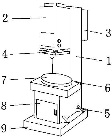
[0019] Such as Figure 1-5 As shown, an automatic continuous stamping production equipment includes an equipment support column 1, a hydraulic tank 2 is fixedly installed on the front outer surface of the equipment support column 1 near the upper end, and a hydraulic tank 2 is fixedly installed on the rear end outer surface of the equipment support column 1 near the upper end. The power supply box 3 and the lower part of the hydraulic box 2 are provided with a hydraulic plate 4, and the lower part of the hydraulic plate 4 is located on the outer surface of the front end of the equipment support column 1, and a chassis 5 is fixedly installed on the outer surface of the upper end of the chassis 5. 6 is provided with a workbench 7, a dodge door 8 is ...


PUM


Abstract

The invention discloses automatic and continuous punching production equipment. The automatic and continuous punching production equipment comprises an equipment supporting column; a hydraulic tank isfixedly installed at the position, close to the upper end, of the outer surface of the front end of the equipment supporting column; a power supply tank is fixedly installed at the position, close tothe upper end, of the outer surface of the rear end of the equipment supporting column; a hydraulic board is arranged below the hydraulic tank; a case is fixedly installed at the position, below thehydraulic board, of the outer surface of the front end of the equipment supporting column; a supporting board is fixedly installed on the outer surface of the upper end of the case; a workbench is arranged above the supporting board; and a movable door is movably installed in the middle of the outer surface of the front end of the case. The automatic and continuous punching production equipment isprovided with the workbench, an electric lifting rod and a laser emitting opening, continuous punching machining of the punching production equipment can be achieved, people can rapidly fix workpieces conveniently, the calibration difficulty can be reduced, people can finish calibration conveniently, and better use prospects are brought.

Description

technical field [0001] The invention relates to the field of automatic continuous stamping production equipment, in particular to an automatic continuous stamping production equipment. Background technique [0002] Stamping production equipment is a common stamping production equipment used for stamping parts to form parts. With the rapid development of science and technology, people have higher and higher requirements for automated continuous stamping production equipment, resulting in existing stamping production equipment. Can not meet the needs of people; the existing stamping production equipment has certain disadvantages in use, first of all, the existing stamping production equipment cannot process workpieces continuously, which greatly reduces the practicability of the stamping production equipment, and secondly, the stamping production equipment during use Fixing the workpiece is inconvenient and does not meet people's requirements. Finally, the existing stamping pr...

Claims


Application Information

Patent Timeline
Patent Type & Authority Applications(China)
IPC IPC(8): B30B1/32B30B15/00B30B15/26B21D43/00B21D43/14
CPCB30B1/32B21D43/003B21D43/14B30B15/00B30B15/0076B30B15/26
Inventor 陈小辉
Owner 陈小辉
Features
  • R&D
  • Intellectual Property
  • Life Sciences
  • Materials
  • Tech Scout
  • Unparalleled Data Quality
  • Higher Quality Content
  • 60% Fewer Hallucinations
Learn More