Medium transport device and image reading apparatus

A medium conveying and medium technology, applied in the field of image reading devices, can solve problems such as no contribution

Active Publication Date: 2018-11-13
SEIKO EPSON CORP
View PDF7 Cites 4 Cited by
  • Summary
  • Abstract
  • Description
  • Claims
  • Application Information

AI Technical Summary

Problems solved by technology

[0008] In addition, the original document stopper 34 described in the above-mentioned Patent Document 1 does not contribute at all to such a requirement, and there is room for improvement.

Method used


Image

  • Medium transport device and image reading apparatus
  • Medium transport device and image reading apparatus
  • Medium transport device and image reading apparatus

Examples


no. 1 example

[0092] Overview of the printer

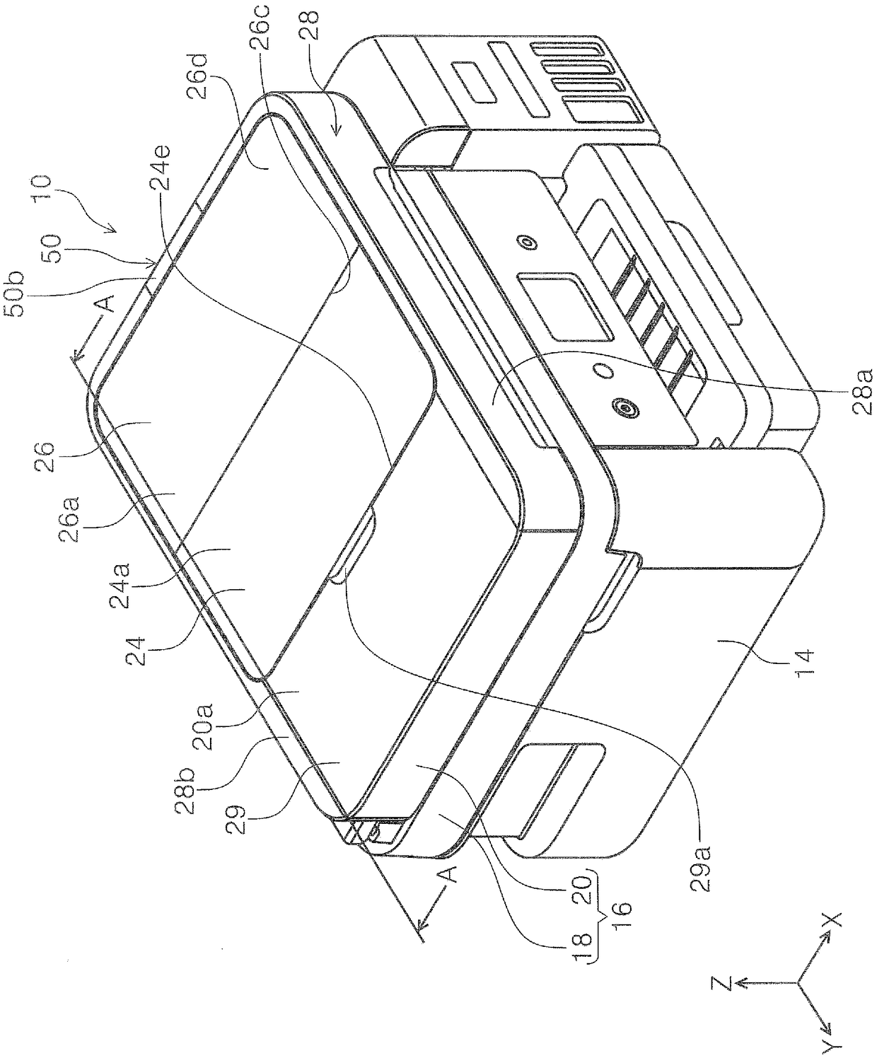
[0093] refer to figure 1 The overall configuration of the printer 10 will be described. The printer 10 is configured as an inkjet printer as an example of a recording device. The printer 10 is configured as an all-in-one machine including a device main body 14 and a scanner unit 16 as an image reading device.

[0094] In this embodiment, the scanning unit 16 is rotatably connected to the rear end of the device body 14 in the depth direction of the device. Although not shown in the figure, the upper part of the device body 14 can The exposed way constitutes. The scanning unit 16 includes: a scanner body 18 and an ADF (Automatic Document Feeding Device) section 20 as a "medium feeding device".

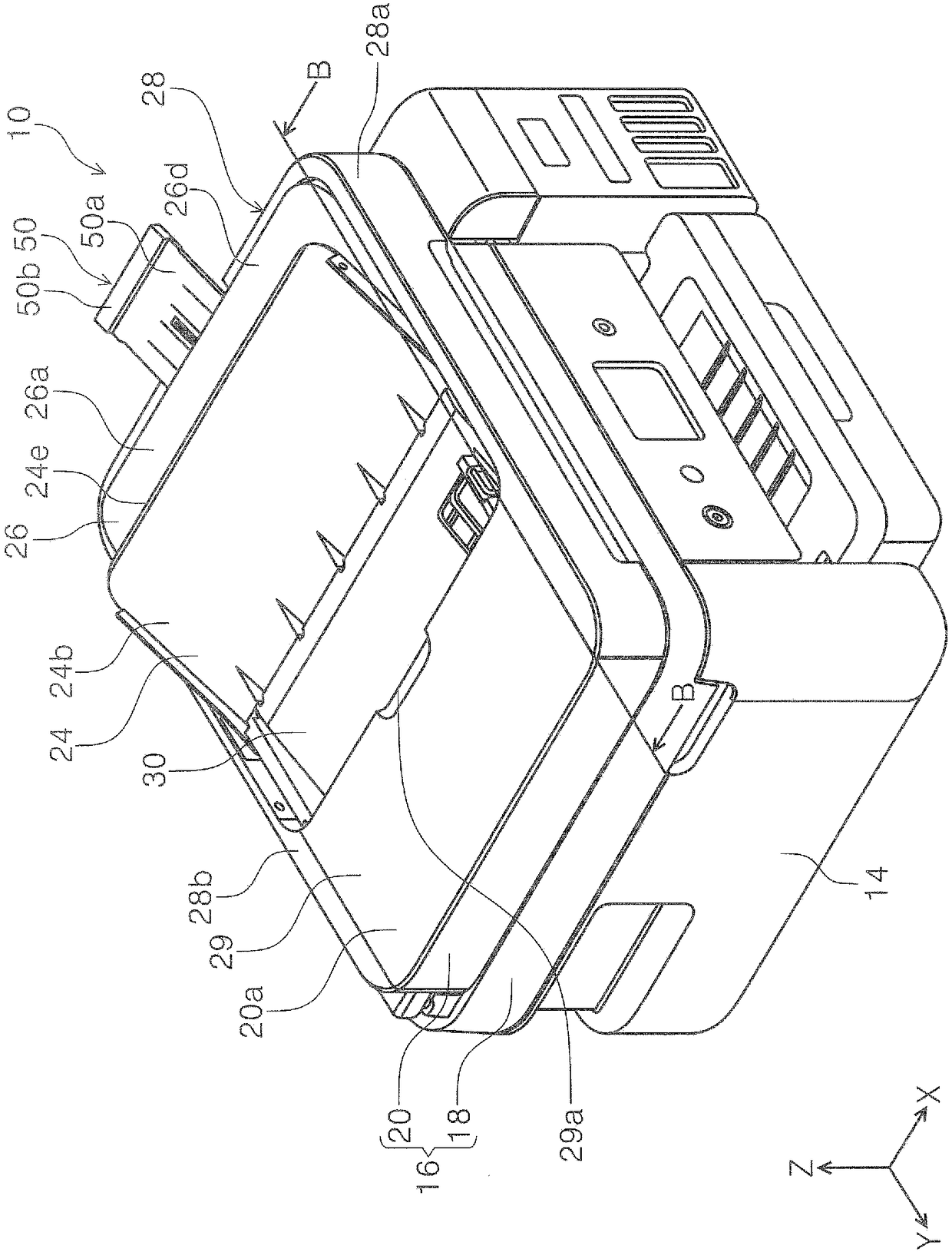
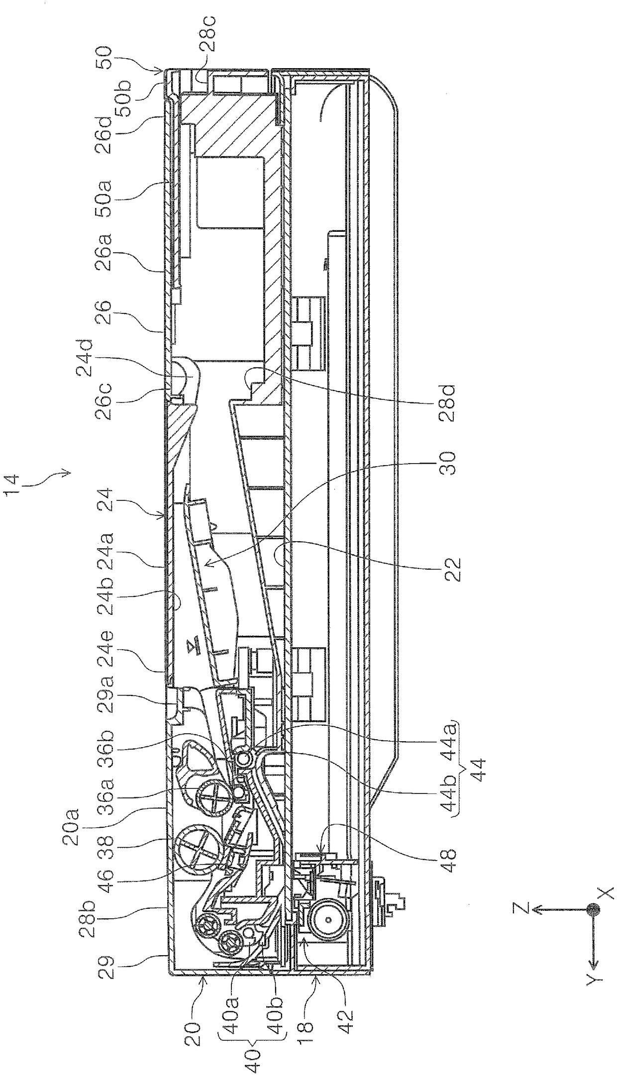
[0095] The ADF unit 20 is rotatably connected to the end portion of the scanner main body 18 on the rear side in the device depth direction. By rotating the ADF unit 20 to the device rear side, the document loading surface 22 ( image 3 and Figure ...

no. 2 example

[0129] Next, at Figure 11 to Figure 14 The second embodiment will be described in . This embodiment differs from the first embodiment in that a link mechanism 56 is provided between the sub-tray 50 and the base frame 28 . In addition, in Figure 13 and Figure 14 In FIG. 2 , illustration of the supply tray 24 and the document support tray 26 is omitted.

[0130] exist Figure 13 Among them, the link shaft 52 extending in the X-axis direction is provided at the +Y-axis direction side end portion of the sub-tray 50 . In the base frame 28, link grooves 54 are formed on both side walls 28e in the X-axis direction, respectively. In this embodiment, the connecting rod groove 54 is as Figure 11 As shown, it extends in the -Y-axis direction, and is inclined so as to descend toward the -Z-axis direction at an angle θ with respect to the Y-axis direction (horizontal direction). Each link groove 54 is engaged with an upper end portion 54 a in the X-axis direction of the link sha...

no. 3 example

[0150] Next, at Figure 17 to Figure 19 The third embodiment will be described in . This embodiment differs from the second embodiment in that the link groove provided on the side wall of the base frame is provided on the document support tray.

[0151] exist Figure 17 In the document support tray 66, a sub-tray 68 is mounted so as to be slidably movable between a storage position and a pull-out position. Specifically, the link groove 66 a is formed in the lower portion of the document support tray 26 . Such as Figure 18 As shown, when the document support tray 66 is in the non-feeding state, the link groove 66a is formed as an obliquely downward groove extending in the Y-axis direction and descending downward from the +Y-axis side toward the -Y-axis side. In the link groove 66a, the end portion on the +Y-axis direction side is the start end portion 66b, and the end portion on the −Y-axis direction side is the end portion 66c.

[0152] A link shaft 68 a that engages wit...


PUM


Abstract

The application discloses a medium transport device and an image reading device. Provided are a medium transport device capable of acheiving improved loading performance of a manuscript and the like to a top surface of the medium transport device and an image reading device. The medium transport device includes a base frame which includes an outer edge forming portion which configures an outer edge of a device top surface, a medium support tray which is capable of switching between a horizontal posture and an inclined posture, the medium support tray forming a portion of a flat device top surface when in the horizontal posture, and a sub-tray which is capable of being displaced between a storage position at which the sub-tray is stored at the lower side of the medium support tray and a pulled-out position at which the sub-tray is pulled out from the lower side of the medium support tray, and supports the medium at the pulled-out position, the sub-tray including a convex portion which configures a portion of the flat device top surface together at the storage position, and the sub-tray being capable of being displaced along a direction that is parallel to the device top surface in astate in which the medium support tray takes the horizontal posture.

Description

technical field [0001] The present invention relates to a medium conveying device for conveying a medium, and an image reading device provided with the medium conveying device. Background technique [0002] A scanner as an example of an image reading device is provided with an automatic document feeder (also referred to as an ADF (Auto Document Feeder)) as a medium feeder, so as to be able to automatically feed and document a plurality of originals. The configuration of the reading method.As the structure of the automatic document feeder, the document is sent out from the paper feed tray, reversed in a U-shape, read the original document, and ejected to the paper output tray. [0003] The paper feed tray or paper output tray of such an automatic document feeder is sometimes provided with a stopper for preventing the document from slipping off the tray. A document stopper 34 included in the document conveying device described in Patent Document 1 is rotatably provided in a r...

Claims


Application Information

Patent Timeline
Patent Type & Authority Applications(China)
IPC IPC(8): B65H1/04B65H3/06B65H5/06
CPCB65H1/04B65H3/06B65H5/06B65H2801/03B65H2403/533B65H2405/11164B65H2405/324B65H2405/3321B65H31/02B65H31/24B65H2301/4212B65H2405/11151B65H2405/12B65H2405/332H04N1/00798H04N1/00623B41J13/103B65H31/20B41J13/106
Inventor 山田克己小崎考平宫本真太郎
Owner SEIKO EPSON CORP
Why Eureka
Try Eureka