
Discharging device for textile fabric processing

A technology for weaving fabrics and discharging devices, which is applied in thin material handling, transportation and packaging, winding strips, etc., can solve the problems of wasting time and reducing production efficiency, and achieve the effect of reducing time and improving production efficiency.

Pending Publication Date: 2018-11-13
AOYANG GRP CO LTD
View PDF0 Cites 0 Cited by
  • Summary
  • Abstract
  • Description
  • Claims
  • Application Information

AI Technical Summary

Problems solved by technology

[0003] In the existing processing process, when a batch of fabrics on the discharge device is finished, the staff will remove the hollow cylinder used to wind the fabrics, and then reinstall the new fabrics on the discharge device, which wastes time and is easy to reduce Productivity

Method used

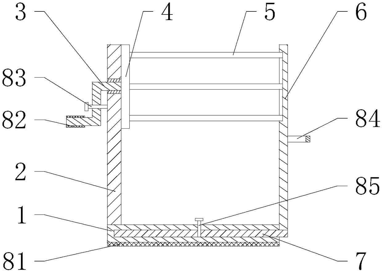
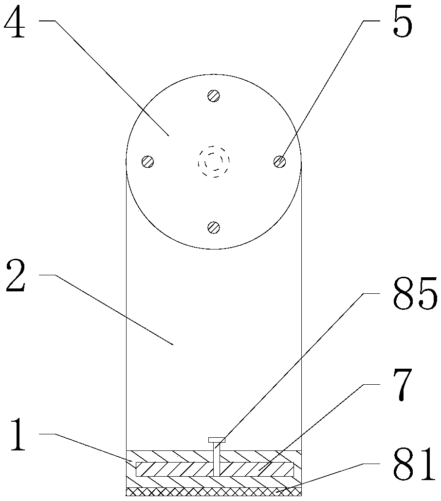
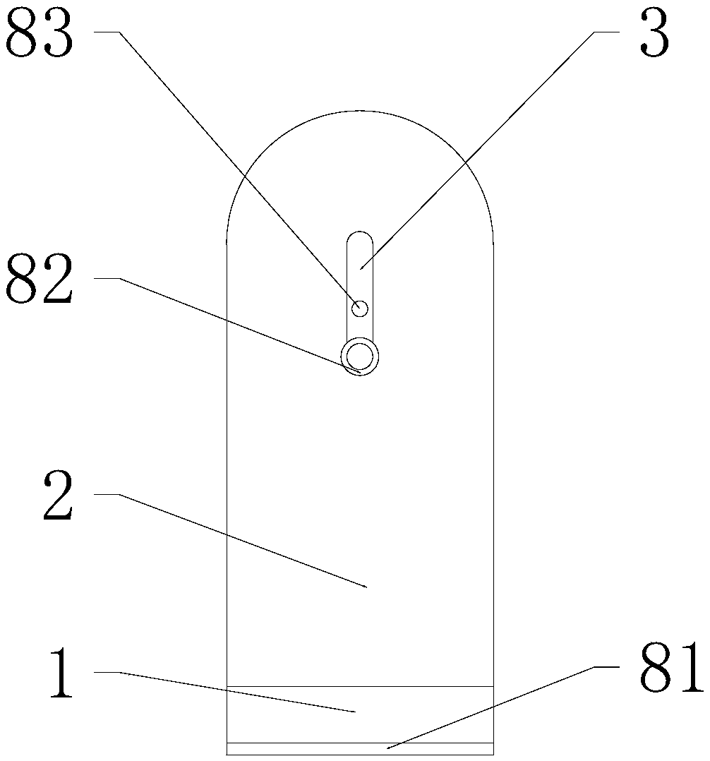

Image

  • Discharging device for textile fabric processing
  • Discharging device for textile fabric processing
  • Discharging device for textile fabric processing

Examples


Embodiment Construction

[0019] In order to make the technical means, creative features, goals and effects achieved by the present invention easy to understand, the present invention will be further described below in conjunction with specific embodiments.

[0020] see Figure 1-Figure 3 , the present invention provides a technical solution: a discharge device for textile fabric processing, including a hollow load-bearing base plate 1, a vertical plate 2, a vertical plate 2 6 and an extension plate 7, and the upper end of the hollow load-bearing base plate 1 is welded with a vertical plate 2 , the right end of the vertical plate 2 is installed with a circular plate 4, the left end of the circular plate 4 is welded with a turning handle 3, the rotating handle 3 is installed in the inside of the vertical plate 2 through a bearing and extends out of the left end of the vertical plate 2, and the right end of the circular plate 4 is welded with a rotating shaft 5 , the rotating shaft 5 is installed on the ...


PUM


Abstract

The invention provides a discharging device for textile fabric processing. The discharging device comprises a hollow bearing bottom plate, a first stand plate, a rotary handle, a round plate, a rotaryshaft, a second stand plate and an extending plate. The first stand plate is welded to the upper end of the hollow bearing bottom plate, and the round plate is mounted at the right end of the first stand plate. The rotary handle is welded to the left end of the round plate, and the rotary handle is mounted in the first stand plate through a bearing and extends out of the left end of the first stand plate. The rotary shaft is welded to the right end of the round plate, the rotary shaft is mounted at the left end of the second stand plate and extends into the second stand plate. The extending plate is welded to the lower end of the second stand plate, and the extending plate is mounted in the hollow bearing bottom plate through a sliding rail and extends out of the right end of the hollow bearing bottom plate. The second stand plate is mounted at the right end of the hollow bearing bottom plate. The discharging device is easy to operate and convenient to use, and production efficiency is effectively improved.

Description

technical field [0001] The invention relates to a feeding device for textile cloth processing, which belongs to the technical field of textiles. Background technique [0002] Textile cloth is usually wound on a hollow cylinder. During processing, the hollow cylinder is placed on a discharge device, and the fabric is pulled out for processing while the hollow cylinder rotates and discharges. [0003] In the existing processing process, when a batch of fabrics on the discharge device is finished, the staff will remove the hollow cylinder used to wind the fabrics, and then reinstall the new fabrics on the discharge device, which wastes time and is easy to reduce Productivity. Contents of the invention [0004] Aiming at the deficiencies in the prior art, the object of the present invention is to provide a discharge device for textile fabric processing to solve the problems raised in the above-mentioned background technology. The present invention is simple to operate, easy t...

Claims


Application Information

Patent Timeline
IPC IPC(8): B65H19/10B65H16/06B65H16/10
CPCB65H16/06B65H16/10B65H19/10
Inventor 沈学如
Owner AOYANG GRP CO LTD
Learn More