Unlock instant, AI-driven research and patent intelligence for your innovation.

Push-and-pull mechanism of lock and lock

A technology of push-pull mechanism and pull parts, which is applied in the direction of lock shells, building locks, building structures, etc., which can solve problems such as insufficient safety, human injury, and potential safety hazards, and achieve simple operation, high safety, and avoid wear and tear Effect

Inactive Publication Date: 2018-11-13
SHENZHEN KAADAS INTELLIGENT TECH CO LTD
View PDF9 Cites 2 Cited by
  • Summary
  • Abstract
  • Description
  • Claims
  • Application Information

AI Technical Summary

Problems solved by technology

[0003] Generally, for the convenience of use, the handle of the lock is protruded outside the panel, which seriously affects the simplicity and beauty of the appearance of doors and windows
At the same time, when the human body collides with the handle, the protruding handle will cause greater damage to the human body
Furthermore, the protruding handle also provides a fulcrum that can be pried for the abnormal opening of the lock, making the lock vulnerable to damage by external forces, and there is a greater potential safety hazard
The handle of some locks is accommodated in the panel to hide the handle, and one end of the handle is connected to the panel in rotation, and the other end of the handle is pulled to make the end of the handle close to the panel rotate relative to the panel, so that the handle Hands are exposed to push and pull doors and windows, but long-term lifting of the handle and the force on the handle is difficult to control will easily cause the end of the handle close to the panel to wear or break, requiring frequent replacement of the panel or handle, which seriously affects the normal use of the lock. security is not high enough

Method used


Image

  • Push-and-pull mechanism of lock and lock
  • Push-and-pull mechanism of lock and lock
  • Push-and-pull mechanism of lock and lock

Examples


Embodiment Construction

[0029] In order to facilitate the understanding of the present invention, the present invention will be described more fully below with reference to the associated drawings. Preferred embodiments of the invention are shown in the accompanying drawings. However, the present invention can be embodied in many different forms and is not limited to the embodiments described herein. On the contrary, these embodiments are provided to make the understanding of the disclosure of the present invention more thorough and comprehensive.

[0030] Unless otherwise defined, all technical and scientific terms used herein have the same meaning as commonly understood by one of ordinary skill in the technical field of the invention. The terms used herein in the description of the present invention are for the purpose of describing specific embodiments only, and are not intended to limit the present invention.

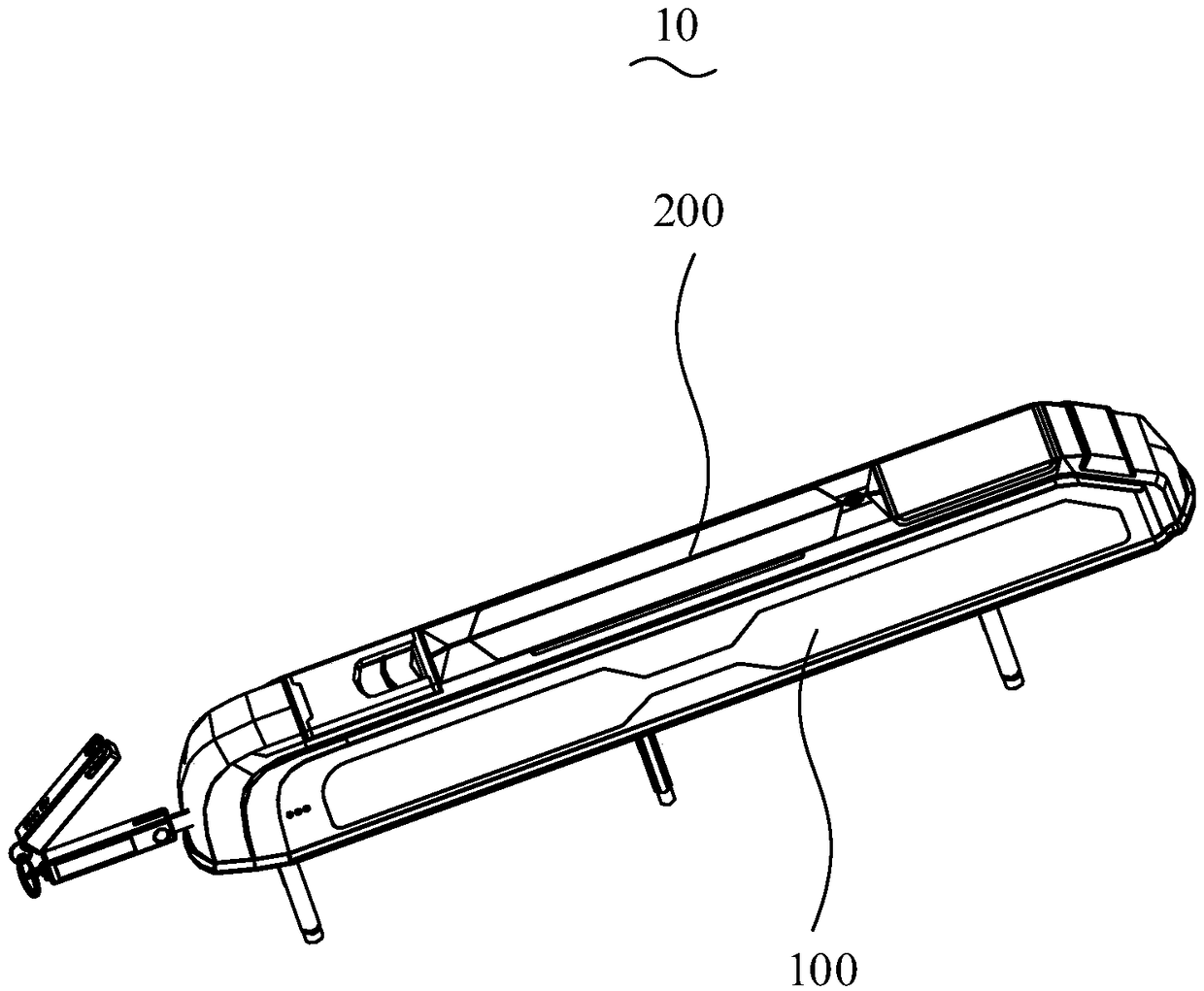
[0031] Such as figure 1 As shown, a lock according to an embodiment includes a lock...


PUM


Abstract

The invention relates to a push-and-pull mechanism of a lock and the lock. The push-and-pull mechanism comprises a panel and a push-and-pull structure. A containing groove is formed in the panel. Thepush-and-pull structure comprises a push-and-pull part, a connecting part and a power assembly; the position of the push-and-pull part corresponds to that of the containing groove, the push-and-pull part is movably connected with the panel, and the push-and-pull part can move in the direction of the interior or the exterior of the containing groove so that the push-and-pull part can be completelycontained in the containing groove or stretch out from the containing groove. The connecting part is rotationally connected with the panel and movably connected with the push-and-pull part, and the connecting part can rotate relative to the panel to drive the push-and-pull part to move. The power assembly can drive the connecting part to rotate. According to the push-and-pull mechanism, the push-and-pull part can be hidden well, and wear to the push-and-pull part is small.

Description

technical field [0001] The invention relates to the technical field of locks, in particular to a push-pull mechanism of a lock and the lock. Background technique [0002] With the continuous development of society, the types and specifications of locks are also increasing dramatically. Usually, the lock consists of a handle, a panel and a lock body. The closing of the lock body can be realized by the rotation of the handle, and the handle can also be used as a fulcrum of the hand to push and pull the door and window to realize the opening or closing of the door and window. [0003] Generally, for ease of use, the handle of the lock is protruded outside the panel, which seriously affects the succinct and attractive appearance of the doors and windows. At the same time, when the human body collides with the handle, the protruding handle will cause greater damage to the human body. Furthermore, the protruding handle also provides a fulcrum that can be pried for the abnormal ...

Claims


Application Information

Patent Timeline
IPC IPC(8): E05B15/00E05B9/00
CPCE05B9/002E05B15/00
Inventor 苏祺云彭文清龚本维沈耀益
Owner SHENZHEN KAADAS INTELLIGENT TECH CO LTD
Features
  • R&D
  • Intellectual Property
  • Life Sciences
  • Materials
  • Tech Scout
  • Unparalleled Data Quality
  • Higher Quality Content
  • 60% Fewer Hallucinations
Learn More