
Rotation-prevention-type hub bolt

A wheel hub bolt, anti-rotation technology, applied in the directions of bolts, screws, nuts, etc., can solve the problems of poor anti-rotation effect of wheel bolts, insufficient operator experience, increase maintenance and replacement costs, etc., to improve waterproof and anti-rust performance, guarantee Vertical force, flexible effect

Pending Publication Date: 2018-11-13
嘉兴同辉汽配有限公司
View PDF0 Cites 0 Cited by
  • Summary
  • Abstract
  • Description
  • Claims
  • Application Information

AI Technical Summary

Problems solved by technology

[0003] Now the axle hub wheel bolts of heavy-duty vehicles, the structure is mostly processed into polished rods between the head of the bolt and the threaded section. When installing, the wheel bolts are pressed into the bolt holes on the wheel hub to form an interference fit. And the head of the wheel bolt is made into a circular milling plane to cooperate with the notch on the wheel hub to stop rotation, but the wheel bolt stop effect of this structure is not good. After the nut is tightened, the wheel bolt will rotate, and even the wheel bolt will appear After the rotation, the flat seam on the hub is severely worn and deformed, which makes the connection invalid
And during the fastening operation, if the vertical force of the bolt and the threaded hole cannot be guaranteed, resulting in oblique force or the operator is inexperienced or uses too much force, the fragile threaded hole will slip.
[0004] In addition, after the hub bolts are installed on the car wheels, they are exposed to the air for a long time, especially in the humid rainy season, they are often rusted and damaged, which affects the service life of the bolts and increases the cost of maintenance and replacement.

Method used


Image

  • Rotation-prevention-type hub bolt

Examples


Embodiment Construction

[0017] In order to make the object, technical solution and advantages of the present invention clearer, the present invention will be further described in detail below with reference to the accompanying drawings and embodiments. However, it should be understood that the specific embodiments described here are only used to explain the present invention, and are not intended to limit the scope of the present invention. Also, in the following description, descriptions of well-known structures and techniques are omitted to avoid unnecessarily obscuring the concept of the present invention.

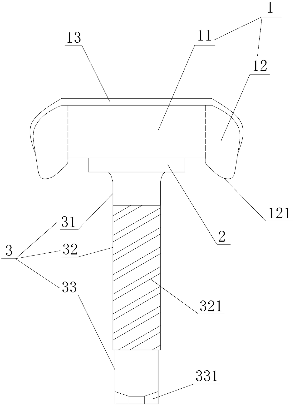
[0018] refer to figure 1 , the embodiment of the present invention provides a non-rotating hub bolt, including a bolt head mechanism 1, a connecting block 2 and a screw mechanism 3, the bolt head mechanism 1 and the connecting block 2 below are punched and riveted by a punching machine, and the described The connecting block 2 and the lower screw mechanism 3 are stamped and riveted by a punch...


PUM


Abstract

The invention discloses a rotation-prevention-type hub bolt. The rotation-prevention-type hub bolt comprises a bolt head mechanism, a connection block and a screw rod mechanism; the bolt head mechanism comprises a bolt head base and bolt head rotation-prevention parts; the bolt head rotation-prevention parts are arranged on the left and right ends of the bolt head base; a stabilization part is arranged on each bolt head rotation-prevention part; and each stabilization part is an arc surface and the radian of each stabilization part is matched with the arc surface of a hub which is in contact with the stabilization part. According to the rotation-prevention-type hub bolt, through the arc structures of the stabilization parts on the rotation-prevention parts of the bolt head, the bolt head can be well matched with the arc surface of the hub; a guiding unthreaded rod section of which the diameter is smaller than that of the outer thread of the bolt is arranged below the screw rod mechanism, and the guiding unthreaded rod perform vertical guiding before the bolt is engaged with a threaded hole, so that vertical stressing of the bolt is ensured, and the probability thread slippery is reduced; the bolt head base is matched with the bolt head rotation-prevention parts, so that an umbrella-shaped shielding zone is formed above the connection block and shields the connection block and the screw rod mechanism; and rainwater is prevented from permeating, and the bolt is prevented from being rusted and corroded by rainwater.

Description

【Technical field】 [0001] The invention relates to the technical field of hub bolts, in particular to a non-rotating hub bolt. 【Background technique】 [0002] Hub bolts are high-strength bolts that connect the wheels of the vehicle. The connection position is the hub unit bearing of the wheel. Generally, miniature vehicles use grade 10.9, and large and medium-sized vehicles use grade 12.9. The structure of hub bolts is generally knurled key gear, thread gear and a cap head, T-shaped head hub bolts Most of them are above grade 8.8, responsible for the large torsion connection between the wheel hub and the axle. In the past, single row tapered roller or ball bearings were mostly used in pairs. With the development of technology, cars have widely used car hub units. [0003] Now the axle hub wheel bolts of heavy-duty vehicles, the structure is mostly processed into polished rods between the head of the bolt and the threaded section. When installing, the wheel bolts are presse...

Claims


Application Information

Patent Timeline
Patent Type & Authority Applications(China)
IPC IPC(8): F16B35/06F16B39/282F16B23/00F16B33/06
CPCF16B23/0015F16B23/0023F16B33/06F16B35/06F16B39/282
Inventor 蒋雪良
Owner 嘉兴同辉汽配有限公司
Learn More