
An adjustable elastic support wire clip

An elastic support and wire clip technology, applied in the direction of overhead lines, etc., can solve the problems of high installation accuracy, lack of yaw angle, weak connection, etc., to avoid excessive wear, improve stress conditions, and simplify installation. The effect of craftsmanship

Active Publication Date: 2016-04-13
CHINA RAILWAY HIGH SPEED ELECTRIFICATION EQUIP CORP LTD
View PDF5 Cites 0 Cited by
  • Summary
  • Abstract
  • Description
  • Claims
  • Application Information

AI Technical Summary

Problems solved by technology

The current clamp has the function of adjusting up and down, but does not have the function of adjusting the yaw angle, so the requirements for the accuracy of the relevant support structure and installation accuracy are very high; the connecting shaft is positioned through the gap between the bolts on the anti-rotation clamping plate, Inaccurate positioning and weak connection

Method used


Image

  • An adjustable elastic support wire clip
  • An adjustable elastic support wire clip

Examples


Embodiment Construction

[0021] Embodiments of the present invention will be described in further detail below in conjunction with the accompanying drawings.

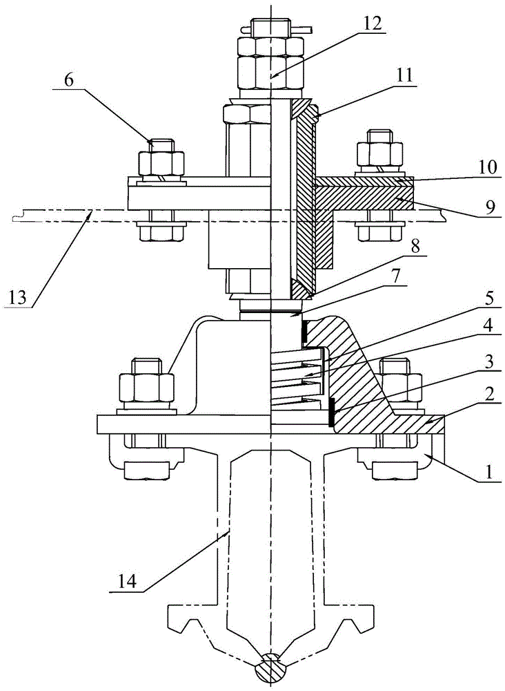
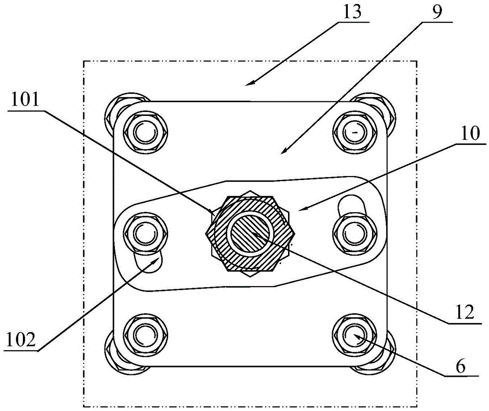
[0022] Such as Figure 1 to Figure 2 As shown, an adjustable elastic support clamp includes an anti-rotation splint 1, a clamp body 2, an elastic element 4, an anti-wear sheath 5, a connecting shaft 7, a spherical pad 8, a support threaded sleeve 9, and an anti-rotation card. The plate 10 and the adjusting sleeve 11, the connecting shaft 7 connects the adjusting sleeve 11 and the clamp body 2 from top to bottom. In this embodiment, the connecting shaft 7 is made of stainless steel machining, and the wire The clamp body 2 is manufactured by an aluminum alloy casting process, and the side of the clamp body 2 is provided with two reinforcing ribs to increase the safety and reliability of the product.

[0023] In the lower part of the supporting wire clamp, the part of the connecting shaft 7 located in the wire clamp body 2 is also sleeved with an...


PUM


Abstract

The invention relates to an adjustable and elastic supporting wire clamp, and relates to the field of rigid suspension systems of electrified railways. A connecting shaft is connected with an adjusting sleeve and a wire clamp body in a vertically penetrating mode. An elastic element is arranged on the portion, located inside the wire clamp body, of the connecting shaft in a sleeved mode. The two sides of the bottom of the wire clamp body are respectively provided with an anti-rotation clamping plate. The adjusting sleeve is provided with a supporting thread sleeve and an anti-rotation blocking board in a sleeved mode, wherein the anti-rotation blocking board is arranged on the supporting thread sleeve in an overlaid mode. A spherical cushion block is arranged between the connecting shaft and each end opening of the adjusting sleeve. The adjustable and elastic supporting wire clamp is accurate in positioning, solid in connection and capable of adjusting the deflection angle.

Description

technical field [0001] The invention relates to the field of rigid suspension systems for electrified railways, in particular to an adjustable elastic support clamp. Background technique [0002] In the rigid suspension system, the wire clamp is installed on the rotatable cantilever to support the suspension busbar. There are many kinds of wire clamp product structures, which are mainly used in the rigid suspension system of urban rail transit and electrified railway. Among them, in the rigid suspension system of electrified railway, the wire clip is installed on the rotatable cantilever, and the busbar is fixed on the wire clip, and the displacement caused by the thermal expansion and cold contraction of the busbar can be adapted by the rotation of the cantilever. The current clamp has the function of adjusting up and down, but does not have the function of adjusting the yaw angle, so the requirements for the accuracy of the relevant support structure and installation accur...

Claims


Application Information

Patent Timeline
Patent Type & Authority Patents(China)
IPC IPC(8): B60M1/20
Inventor 林建李忠齐杨旭尧闫涛邓相龙李立
Owner CHINA RAILWAY HIGH SPEED ELECTRIFICATION EQUIP CORP LTD
Learn More