Textile equipment

A textile equipment and end face technology, applied in the field of textile equipment, can solve the problems of cumbersome cleaning operation steps, lack of self-cleaning function, cumbersome installation steps, etc., to improve the efficiency of scraping dust, improve the scope of use of lighting, and simple installation steps Effect

Inactive Publication Date: 2018-11-13
陈俊兆
View PDF3 Cites 0 Cited by
  • Summary
  • Abstract
  • Description
  • Claims
  • Application Information

AI Technical Summary

Problems solved by technology

[0002] Textile equipment refers to various mechanical equipment required to process natural fibers or chemical fibers into textiles. LED lighting is often installed on textile equipment. Current LED lighting is usually installed on textile equipment through screws and bolts. The installation The steps are cumbersome, and other tools need to be used for disassembly when maintenance is required, which greatly reduces the work efficiency of the staff. Moreover, the current LED lamp body is usually fixed, and the lighting range is small. Moreover, the existing LED lamp body does not have Self-cleaning function, cumbersome cleaning operation steps

Method used


Image

  • Textile equipment
  • Textile equipment

Examples


Embodiment Construction

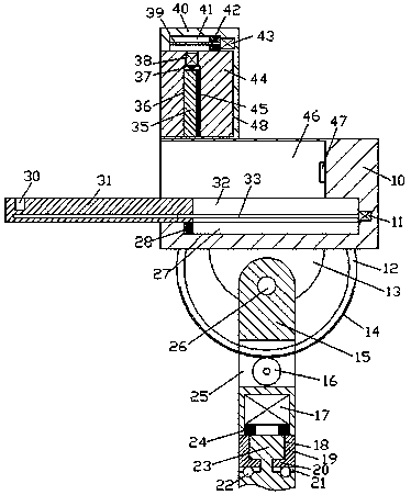
[0016] Combine below Figure 1-2 The present invention will be described in detail.

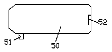
[0017] refer to Figure 1-2 , a textile equipment according to an embodiment of the present invention, comprising a fixing frame 10 and an LED lamp body 50 installed in the fixing frame 10, a locking device is provided in the left end surface of the fixing frame 10, A top frame 40 is fixed on the left side of the top end surface of the fixing frame 10, and a first sliding groove 48 is arranged in the left end surface of the top frame 40, and a first sliding block is installed in the first sliding groove 48 for sliding fit. 44, the inner top wall of the first sliding groove 48 is provided with a second sliding groove 41, and the second sliding groove 41 is slidingly fitted with a second bottom end surface fixedly connected with the top end surface of the first sliding block 44. Sliding block 42, the second sliding block 42 is internally threaded and fitted with a first screw rod 39, the left...


PUM


Abstract

The invention discloses textile equipment. The textile equipment comprises a mounting rack and an LED lamp body mounted in the mounting rack. A locking and fixing device is arranged in the end face ofthe left side of the mounting rack. The left side of the top end face of the mounting rack is provided with a top frame. The end face of the left side of the top frame is internally provided with a first sliding groove. A first sliding block is mounted in the first sliding groove in a sliding fit mode. The internal top wall of the first sliding groove is provided with a second sliding groove. A second sliding block of which the bottom end face is fixedly connected with the top end face of the first sliding block is mounted in the second sliding groove in a sliding fit mode. A first screw rodis mounted in the second sliding block in a screw-thread fit mode. The extension tail end of the left side of the first screw rod is connected with the inner wall of the left side of the second sliding groove in a rotating fit mode. The extension tail end of the right side of the first screw rod is in power connection with a first motor in a matched mode.

Description

technical field [0001] The invention relates to the textile field, in particular to a textile equipment. Background technique [0002] Textile equipment refers to various mechanical equipment required to process natural fibers or chemical fibers into textiles. LED lighting is often installed on textile equipment. Current LED lighting is usually installed on textile equipment through screws and bolts. The installation The steps are cumbersome, and other tools need to be used for disassembly when maintenance is required, which greatly reduces the work efficiency of the staff. Moreover, the current LED lamp body is usually fixed, and the lighting range is small. Moreover, the existing LED lamp body does not have Self-cleaning function, the cleaning operation steps are cumbersome. Contents of the invention [0003] The object of the present invention is to provide a weaving device for overcoming the above-mentioned defects in the prior art. [0004] A textile equipment accor...

Claims


Application Information

Patent Timeline
Patent Type & Authority Applications(China)
IPC IPC(8): F21S8/00F21V19/00F21V21/002F21V21/15F21V23/06F21V33/00B08B1/00F21Y115/10
CPCF21S8/00B08B1/005B08B1/008F21V19/0025F21V21/002F21V21/15F21V23/06F21V33/00F21Y2115/10
Inventor 陈俊兆
Owner 陈俊兆
Why Eureka
Try Eureka