
LED streetlamp unit

A technology of LED street lamps and lampposts, applied in the field of lighting, can solve problems such as easy to touch conductive parts, reduce maintenance efficiency, and hidden safety hazards, so as to improve the stability and accuracy of installation, improve the safety of power supply connections, and improve The effect of installation efficiency

Inactive Publication Date: 2017-06-13
宁波鄞州义旺电子科技有限公司
View PDF5 Cites 9 Cited by
  • Summary
  • Abstract
  • Description
  • Claims
  • Application Information

AI Technical Summary

Problems solved by technology

Solar street lights must use solar cell components to provide electrical energy. For different regions and seasons, the installation inclination and azimuth of solar cell components are different. Traditional solar LED street lights have a single fixing method and complex structures. The adjustment angle is limited, so Can not get sufficient lighting effect, so can not fully convert, resulting in low solar energy conversion utilization rate, at the same time, the existing solar LED street lights are cumbersome and complicated to install, and it is easy to touch the conductive parts during maintenance, which is easy to induce electric shock accidents Occurrence, there is a large potential safety hazard, while greatly reducing the efficiency of maintenance

Method used


Image

  • LED streetlamp unit
  • LED streetlamp unit
  • LED streetlamp unit

Examples


Embodiment Construction

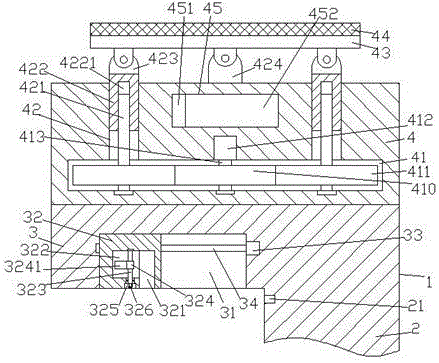
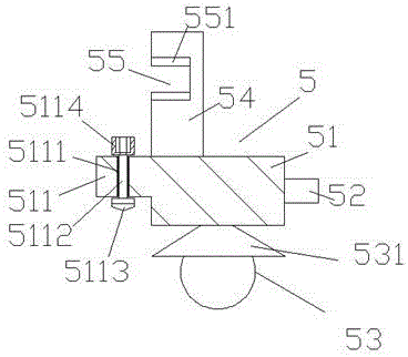
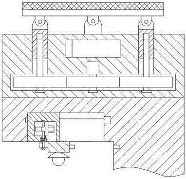
[0024] Such as Figure 1-Figure 8 As shown, an LED street lamp device of the present invention includes a bottom bracket 1, a power storage part 4 and a lamp head 5 fixedly installed on the top end surface of the bottom bracket 1, and a lamp is fixedly installed at the bottom of the right side of the bottom bracket 1. Column 2, the bottom of the lamp column 2 is provided with a lamp holder 20, the left side of the bottom bracket 1 is provided with a push part 3, and a push groove 31 is provided in the end surface of the bottom of the push part 3, and a push groove 31 is provided in the push groove 31. The first screw rod 34 extended left and right, the right side end of the first screw rod 34 is connected with the first driving machine 33, and the pushing groove 31 is provided with a pusher that is connected with the helical pattern of the first screw rod 34. Block 32, the pushing block 32 is provided with a first cavity 322, and the pushing block 32 on the right side of the f...


PUM


Abstract

The invention discloses an LED streetlamp unit, comprising a base, an electricity storage portion fixedly mounted on the top end face of the base, and a lamp cap portion; a lamp post is fixed to the right bottom of the base; a lamp seat is arranged at the bottom of the lamp post; a pushing portion is arranged on the left of the base; a pushing channel is arranged in the bottom end of the pushing portion; a first threaded rod extended to left and right is arranged in the pushing channel, the right end of the first threaded rod is connected with a first drive, a pushing block in threaded connection fit with the first threaded rod is arranged in the pushing channel, a first cavity is arranged in the pushing block, a locking channel having the bottom communicated with the bottom end of the pushing block is arranged in the pushing block on the right of the first cavity, the right end of the first cavity is communicated with the left top of the locking channel, a counterbore is arranged in the bottom end of the pushing block in the bottom of the first cavity, and a first spindle extended to top and bottom is arranged in the first cavity; the LED streetlamp unit is simple in structure and convenient to operate, allows automatic control for pushing fitting, is powered through solar generated electricity, and is energy efficient, environmentally friendly, and high in safety.

Description

technical field [0001] The invention relates to the technical field of lighting, in particular to an LED street lamp device. Background technique [0002] As a clean energy source, solar energy has always been the direction of exploration for human beings to make full use of solar energy. Solar street lights are not affected by power supply, do not consume conventional electric energy, and can be installed on-site as long as the sun resources are sufficient, so they are widely used and concerned. Solar street lights must use solar cell components to provide electrical energy. For different regions and seasons, the installation inclination and azimuth of solar cell components are different. Traditional solar LED street lights have a single fixing method and complex structures. The adjustment angle is limited, so Can not get sufficient lighting effect, so can not fully convert, resulting in low solar energy conversion utilization rate, at the same time, the existing solar LED ...

Claims


Application Information

Patent Timeline
Patent Type & Authority Applications(China)
IPC IPC(8): F21S9/03F21V17/02F21V17/12F21V17/18F21V23/00F21V25/00F21W131/103F21Y115/10
CPCY02B20/72F21S9/032F21V17/02F21V17/12F21V17/18F21V23/003F21V25/00F21W2131/103
Inventor 徐小风
Owner 宁波鄞州义旺电子科技有限公司
Learn More