Marine shafting installation method

An installation method and a shafting technology, applied to ships and other directions, can solve the problems of increasing the construction period, increasing the safety hazards of construction personnel, and many precautions, so as to reduce the difficulty of hoisting, save the docking period, and shorten the construction period.

Active Publication Date: 2020-02-14
JIANGNAN SHIPYARD GRP CO LTD
View PDF5 Cites 9 Cited by
  • Summary
  • Abstract
  • Description
  • Claims
  • Application Information

AI Technical Summary

Problems solved by technology

In this installation method, in order to ensure the accuracy of the shafting installation, after the ship is launched, the shafting installation must also have an underwater flange centering link, which greatly increases the construction period.
In addition, the construction steps of the conventional shafting installation scheme are relatively cumbersome, and there are many precautions. The detachable plates on the main deck need to be designed and reserved as early as possible, and the setting of the detachable plates will also affect the strength of the hull structure.
It is difficult to enter the cabin of large equipment such as main engine, gearbox, shafting, etc., which increases the safety hazards of construction personnel
Moreover, the conventional shafting installation scheme has many procedures and is more prone to errors. This process requires site construction personnel to spend a considerable amount of time and energy to continuously adjust to meet the standards required by the process, which greatly increases the construction of berths and docks. cycle, which affects the project schedule and also increases the project cost

Method used


Image

  • Marine shafting installation method
  • Marine shafting installation method
  • Marine shafting installation method

Examples


Embodiment Construction

[0047] The implementation of the present invention will be illustrated by specific specific examples below, and those skilled in the art can easily understand other advantages and effects of the present invention from the contents disclosed in this specification.

[0048] see Figure 1 to Figure 3 . It should be noted that the structures, proportions, sizes, etc. shown in the drawings attached to this specification are only used to match the content disclosed in the specification, for those who are familiar with this technology to understand and read, and are not used to limit the implementation of the present invention. Limiting conditions, so there is no technical substantive meaning, any modification of structure, change of proportional relationship or adjustment of size, without affecting the effect and purpose of the present invention, should still fall within the scope of the present invention. The disclosed technical content must be within the scope covered. At the sa...


PUM


Abstract

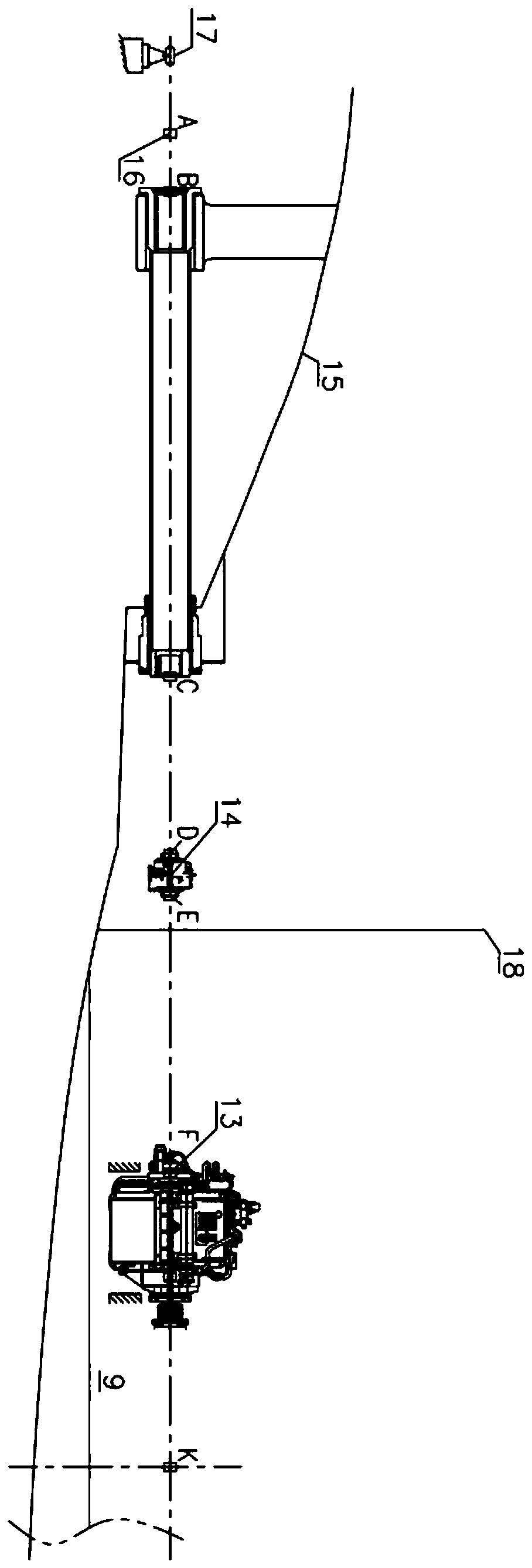
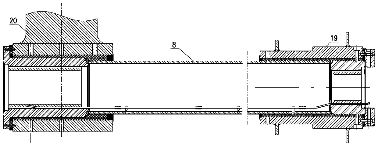
The invention provides a marine shafting installation method comprising the following steps of hoisting an intermediate shaft, a gearbox and a mainframe into a cabin in position before irradiation; centering shafting with equipment by irradiation, and locating and installing a stern shaft tube; primarily locating the intermediate shaft, the gearbox and the mainframe, and performing the connectionand installation work of the shafting; checking the bearing load, and measuring the support reaction of a front bearing and an intermediate bearing of the stern shaft tube and a rear bearing of the gearbox; checking the support reaction with a computed result, and accurately locating the gearbox and the mainframe; and finally finishing installation of the intermediate bearing, the gearbox and themainframe. According to the scheme, the irradiation method with the equipment is invented firstly, and a traditional flange centering scheme is replaced with the method, so that the installation of inspection equipment is more visualized; and the equipment centering and locating accuracy is improved. The gearbox, the mainframe and the intermediate bearing are primarily located in the shipbuildingstage in advance, and the shaft connection is conducted; the shafting installation step is simplified, and the locating time of underwater equipment is shortened; and the shipbuilding period is shortened.

Description

technical field [0001] The invention relates to a shafting installation method of a ship, in particular to a shafting installation method of a ship equipped with a gear box in a propulsion system. Background technique [0002] At present, the propulsion systems widely used in various large official ships are usually arranged with intermediate shafts, hydraulic couplings, intermediate bearings, gearboxes, elastic couplings and main engines. The characteristics of the construction plan steps of the conventional shafting system are as follows: [0003] ① There is a detachable plate on the main deck before the shaft system is illuminated and centered, and the main engine, gear box and intermediate shaft enter the warehouse after the shaft system is illuminated and centered; [0004] ②Use the flange alignment method to align the shafting after launching, initially position the intermediate bearing, the gearbox and the main engine, and then connect the shafts. [0005] ③Precisel...

Claims


Application Information

Patent Timeline
Patent Type & Authority Applications(China)
IPC IPC(8): B63B73/20
Inventor 厚阳刘果
Owner JIANGNAN SHIPYARD GRP CO LTD
Why Eureka
Try Eureka