Near-eye display apparatus and equipment, zooming module and zooming method

A near-eye display and display module technology, which is applied in optics, instruments, nonlinear optics, etc., can solve the problem of low efficiency of zoom adjustment, achieve fast response speed and improve display effect

Pending Publication Date: 2018-11-13
CHENGDU IDEALSEE TECH
View PDF10 Cites 8 Cited by
  • Summary
  • Abstract
  • Description
  • Claims
  • Application Information

AI Technical Summary

Benefits of technology

This technology allows for quick changes between two displays with varying levels of brightness depending on how far they are from each other. It also includes an improved image quality that shows both deep layers within one screen view (the distance) while still maintaining good contrast).

Problems solved by technology

The technical problem addressed in this patented text relates how quickly and efficiently extend/change the focus distance for different levels of detail within a scene being captured by an imagery sensor due to changes made over time caused by movement of the camera's lenses.

Method used


Image

  • Near-eye display apparatus and equipment, zooming module and zooming method
  • Near-eye display apparatus and equipment, zooming module and zooming method
  • Near-eye display apparatus and equipment, zooming module and zooming method

Examples


Embodiment Construction

[0033] The following will clearly and completely describe the technical solutions in the embodiments of the present invention with reference to the accompanying drawings in the embodiments of the present invention. Obviously, the described embodiments are only some, not all, embodiments of the present invention. Based on the embodiments of the present invention, all other embodiments obtained by persons of ordinary skill in the art without creative efforts fall within the protection scope of the present invention.

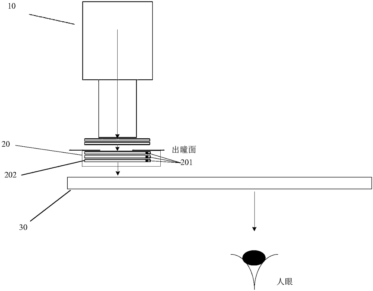
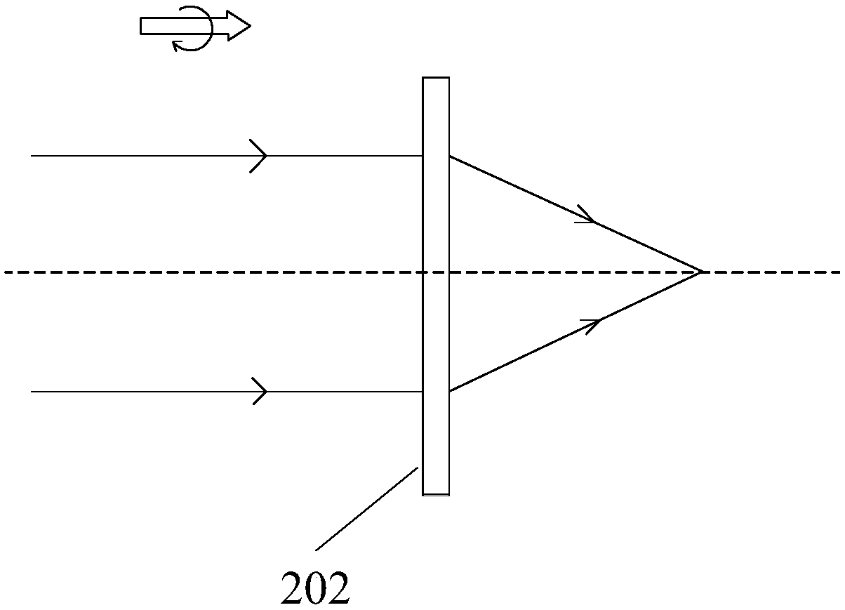
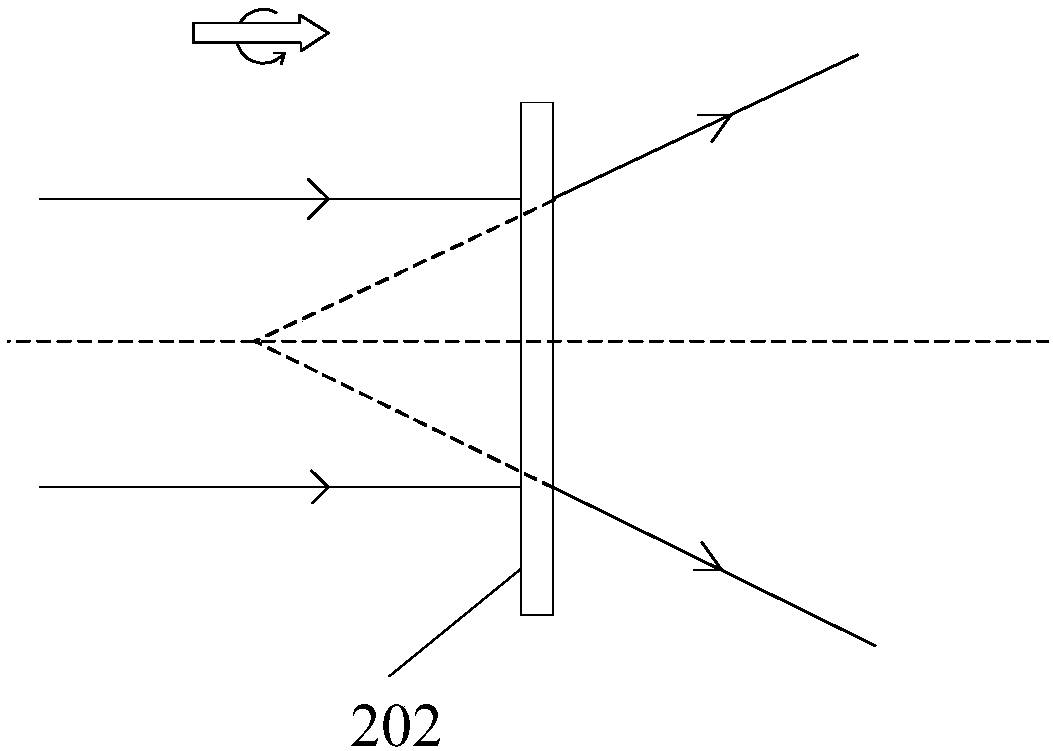
[0034] figure 1 It is a schematic structural diagram of a near-eye display device provided by an embodiment of the present invention. The near-eye display device is provided with a display module 10, a zoom module 20, and a near-eye display flat waveguide 30 in sequence along the optical path. The arrows in the figure indicate the direction of light propagation. Wherein, the zoom module is arranged on the exit pupil surface of the display module, and the zoom modul...


PUM


Abstract

The invention discloses near-eye display apparatus and equipment, a zooming module and a zooming method, for solving the technical problem that a current display device is lower in the zooming effect.The near-eye display apparatus comprises a display module, a zooming module and a near-eye display slab waveguide, wherein the display module, the zooming module and the near-eye display slab waveguide are arranged along the optical path successively; the zooming module comprises an electrode unit and overlapped multi-layer PBLs (Pancharatnam Berry Lens); the electrode unit is used for applying/not applying voltage to the PBLs; each layer of PBL is an optical component which is made of liquid crystal and is based on geometric phase adjustment, and each layer of PBL has one focal power when novoltage is applied; during the projection process, the display module is used to emit circularly polarized light corresponding to an image to be displayed; the zooming module is used to receive the circularly polarized light and control the electrode unit to apply no voltage to N layers of PBLs according to the required focal power; and the total focal power of the N layers of PBLs is corresponding to the required focal power, and when N is greater than or equal to 2, the N layers of PBLs are continuous, and the near-eye display slab waveguide is used to import the light emitted from the zooming module into a human eye.

Description


Claims


Application Information

Patent Timeline
Owner CHENGDU IDEALSEE TECH
Why Eureka
Try Eureka