
Bus automatic switching system and method suitable for remote fault diagnosis

A fault diagnosis and automatic switching technology, applied in the field of vehicle maintenance, can solve problems involving the technical secrets of manufacturers and achieve the effect of remote fault diagnosis

Active Publication Date: 2018-11-13
广州瑞修得信息科技有限公司
View PDF12 Cites 2 Cited by
  • Summary
  • Abstract
  • Description
  • Claims
  • Application Information

AI Technical Summary

Problems solved by technology

[0002] Existing remote diagnosis technologies generally require a clear understanding of the communication protocol with the underlying hardware in order to communicate with the underlying hardware and obtain relevant information, such as collecting vehicle fault codes, you need to know the specific protocols of the relevant models, and these are not disclosed by the manufacturers , involving the manufacturer's technical secrets

Method used


Image

  • Bus automatic switching system and method suitable for remote fault diagnosis
  • Bus automatic switching system and method suitable for remote fault diagnosis
  • Bus automatic switching system and method suitable for remote fault diagnosis

Examples


no. 1 example

[0036] see figure 1 , figure 2 and image 3 .

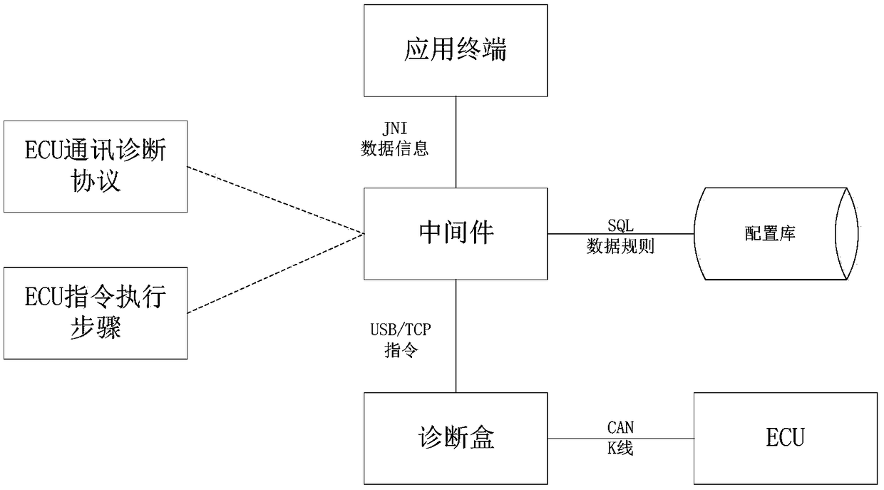
[0037] Such as figure 1 As shown, this embodiment provides an automatic bus switching system suitable for remote fault diagnosis, including: application terminal 100, middleware 200, configuration library 300 and diagnostic box 400; wherein,

[0038] The application terminal 100 is connected to the middleware 200 for selecting a new ECU model to be diagnosed;

[0039] The middleware 200 is used to obtain the communication configuration corresponding to the ECU model from the configuration library 300 according to the ECU model;

[0040] Preferably, the middleware 200 is also used to connect the CAN channel based on the communication configuration, and send a connection command to the diagnostic box 400 to access the CAN data channel;

[0041] The diagnostic box 400 is configured to feed back the connection status to the middleware 200 according to the connection instruction, so that the middleware 200 feeds back the connect...

no. 2 example

[0051] see Figure 4 .

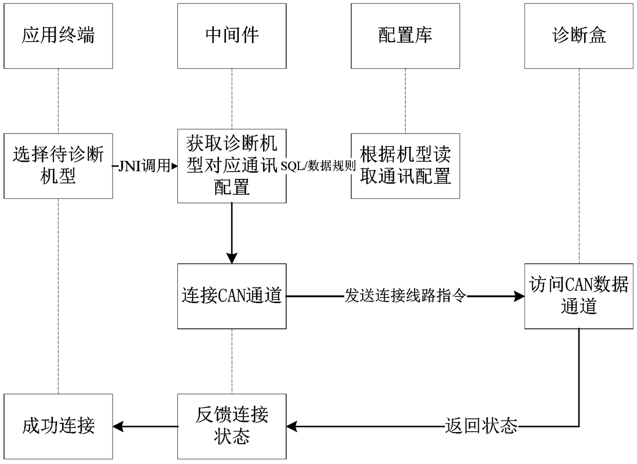
[0052] Such as Figure 4 As shown, this embodiment provides a bus automatic switching method suitable for remote fault diagnosis, which is suitable for execution in computer equipment, and at least includes the following steps:

[0053] S201. The application terminal transmits the ECU model to the middleware according to the selected new ECU model to be diagnosed;

[0054] S202. The middleware acquires the communication configuration corresponding to the ECU model from a configuration library according to the ECU model;

[0055] S203. The middleware connects to the CAN channel based on the communication configuration, and sends a connection command to the diagnostic box to access the CAN data channel;

[0056] S204. The diagnostic box feeds back the connection status to the middleware according to the connection instruction, so that the middleware feeds back the connection status to the application terminal.

[0057] Preferably, the diagnostic box ...


PUM


Abstract

The invention discloses a bus automatic switching system and method suitable for remote fault diagnosis. The system comprises an application terminal, a middle component, a configuration database anda diagnosis box. The application terminal is connected to the middle component and is used for selecting a new ECU model to be diagnosed. The middle component is used to acquire communication configuration corresponding to the ECU model from the configuration database according to the ECU model. The middle component is also used for connecting a CAN channel based on the communication configurationand sending a connection instruction to the diagnosis box so as to access a CAN data channel. The diagnosis box is used for feeding back a connection state to the middle component according to the connection instruction so that the middle component can feed back the connection state to the application terminal. In the invention, through switching among buses, the remote fault diagnosis of variousmodels can be realized.

Description

technical field [0001] The invention relates to the technical field of vehicle maintenance, in particular to a bus automatic switching system and method suitable for remote fault diagnosis. Background technique [0002] Existing remote diagnosis technologies generally require a clear understanding of the communication protocol with the underlying hardware in order to communicate with the underlying hardware and obtain relevant information, such as collecting vehicle fault codes, you need to know the specific protocols of the relevant models, and these are not disclosed by the manufacturers , involving the manufacturer's technical secrets. Therefore, how to separate the protocol from the software, which not only realizes remote fault diagnosis, but also meets the manufacturer's confidentiality requirements for its own protocol, has become the focus of current research. Contents of the invention [0003] The embodiment of the present invention proposes a bus automatic switc...

Claims


Application Information

Patent Timeline
Patent Type & Authority Applications(China)
IPC IPC(8): G05B23/02
CPCG05B23/0213G05B2219/24065
Inventor 李留海
Owner 广州瑞修得信息科技有限公司
Learn More