Automatically magnetically returned bedside chair

An automatic return, magnetic technology, applied in the field of bedside chairs, can solve the problems of reduced ward environment comfort, unfavorable patient rest and recovery, and inconvenient patient rescue, etc., and achieves less mechanical transmission structure, long service life, and low noise. Effect

Pending Publication Date: 2018-11-16
泉州医学高等专科学校
View PDF0 Cites 0 Cited by
  • Summary
  • Abstract
  • Description
  • Claims
  • Application Information

AI Technical Summary

Problems solved by technology

[0002] In the hospital ward, the bedside chairs used by the patient's escorts are more common four-legged chairs. When the person leaves the side of the bed during the escorting process, the escorts often forget to put the chair back. When the situation occurs, the environment in the ward is messy, which is not convenient for the passage of patients, escorts, medical personnel or emergency rescue
On the other hand, the bedside chair needs to be manually moved or pushed back to its original position. On the one hand, it requires extra moving actions by the accompanying staff, causing inconvenience; The comfort level is reduced, which is not conducive to the patient's rest and recovery

Method used


Image

  • Automatically magnetically returned bedside chair
  • Automatically magnetically returned bedside chair
  • Automatically magnetically returned bedside chair

Examples


Embodiment 1

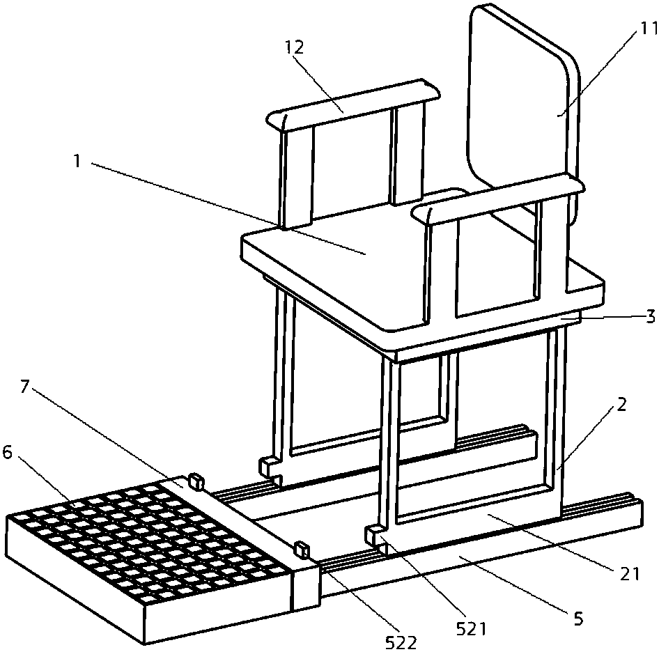
[0041] A bedside chair with automatic magnetic return, comprising a seat surface 1 and a support part 2, the upper end of the support part 2 is connected to the seat surface 1, an elastic device 3 is located between the upper end of the support part 2 and the seat surface 1, and the side of the elastic device 3 is provided There is a first break switch 41; there is a return device 5 fixed to the ground by screws under the support part 2; the return device 5 includes a guide device 51, a first electromagnetic clutch 521 and a second electromagnetic clutch 522, The lower end of the support part 2 is provided with a connecting part 21, the connecting part 21 is movably connected to the guide device 51, and the first electromagnetic clutch 521 is fixedly connected to the connecting part 21; The crossbeam, the surface of the steel crossbeam is wrapped with a buffer layer 7 made of rubber, the surface of the buffer layer 7 has a round hole, and the second dynamic disconnection switch...

Embodiment 2

[0051] The technical scheme described in embodiment two is similar to embodiment one, and its difference is:

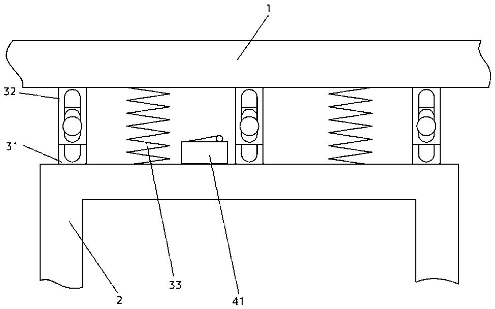
[0052] Such as Figure 4 As shown, in this embodiment, the supporting part 2 and the return device 5 are a set arranged under the seat surface 1 and are symmetrical along the vertical center plane of the seat surface 1 . The support part 2 is a cylinder, the first electromagnetic clutch 521 is located in the middle of its front side, and the second electromagnetic clutch 522 is located in the rear middle of the return device 5, and their magnetic poles have the same direction, that is, the opposite two Magnetic poles attract each other.

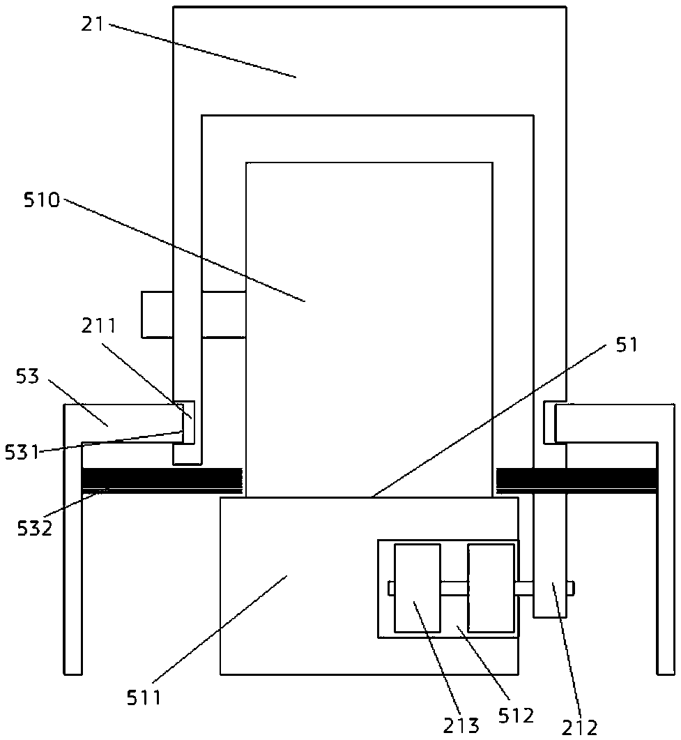
[0053] Such as Figure 5 As shown, in this embodiment, the guide device 51 is a screw 513 arranged horizontally, and the two ends of the screw 513 are provided with support bearings, and the connecting part 21 is located at the bottom of the cylinder of the support part 2 and engaged with the screw 513. Ball nut pair 514. When th...


PUM


Abstract

An automatically magnetically returned bedside chair relates to the technical field of novel medical furniture. The bedside chair comprises a seat surface and a supporting part, the upper end of the supporting part is connected with the seat surface, an elastic device is arranged between the upper end of the supporting part and the seat surface, and the side surface of the elastic device is provided with a first breaking switch; a returning device positioned on the ground is arranged below the supporting part; the returning device comprises a guiding device, first electromagnetic suction devices and second electromagnetic suction devices, connecting parts are arranged at the lower end of the supporting part, the connecting parts are movably connected to the guiding device, and the first electromagnetic suction devices are fixedly connected to the connecting parts; and a buffer layer and a second breaking switch existing in the buffer layer are arranged at the front end of the guiding device, the second electromagnetic suction device is embedded in the buffer layer, and the first breaking switch and the second breaking switch are serially connected with a power supply circuit for the first breaking switch and the second breaking switch. The automatically magnetically returned bedside chair can automatically return, so the disordered degree and ward noises are reduced, and the moving motion of a user is omitted.

Description

technical field [0001] The invention relates to the technical field of novel medical furniture, in particular to a bedside chair with automatic magnetic return. Background technique [0002] In the hospital ward, the bedside chairs used by the patient's escorts are more common four-legged chairs. When the person leaves the side of the bed during the escorting process, the escorts often forget to put the chair back. If the situation occurs, the environment in the ward is messy, which is not convenient for the passage of patients, escorts, medical personnel or emergency rescue. On the other hand, the bedside chair needs to be manually moved or pushed back to its original position. On the one hand, it requires extra moving actions by the accompanying staff, causing inconvenience; The comfort level decreases, which is not conducive to the patient's rest and recovery. Contents of the invention [0003] The purpose of the present invention is to provide a bedside chair with au...

Claims


Application Information

Patent Timeline
Patent Type & Authority Applications(China)
IPC IPC(8): A47C7/00A47C7/50A47C7/62
CPCA47C7/00A47C7/50A47C7/62
Inventor 陈宁静陈梦楠陈日康
Owner 泉州医学高等专科学校
Why Eureka
Try Eureka