Robot face structure and robot

A robot and face technology, applied in manipulators, program-controlled manipulators, manufacturing tools, etc., can solve problems such as the inability to accurately simulate the actions of opening and closing the mouth, and the simulation effect needs to be improved, and achieves high simulation effect, easy to implement, structure simple effect

Pending Publication Date: 2018-11-16
沧州菲漫电子科技有限公司
View PDF0 Cites 8 Cited by
  • Summary
  • Abstract
  • Description
  • Claims
  • Application Information

AI Technical Summary

Problems solved by technology

[0003] In order to make the bionic robot simulate the characteristics of living things more realistically, the bionic robot is usually equipped with a head structure, which can easily simulate the actions of the living thing such as blinking, opening the mouth, turning the head, bowing the head, etc., while the mouth opening actions of the existing bionic robots are mostly For the simple opening and closing action, the mouth simulation mechanism used to realize the mouth opening action generally includes the upper jaw and the lower jaw. For the human mouth structure, due to the special structure of the mouth bones, when the lower jaw is opened relative to the upper jaw, it does not simply rotate around a fixed axis of rotation. Therefore, the requirements for bionics are higher. For robots, such a simple structure cannot accurately simulate human mouth opening and closing movements, and the simulation effect needs to be improved.

Method used


Image

  • Robot face structure and robot
  • Robot face structure and robot
  • Robot face structure and robot

Examples


Embodiment Construction

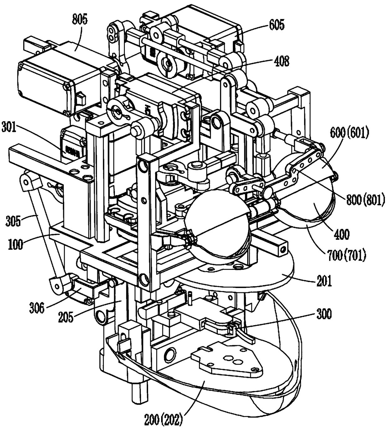
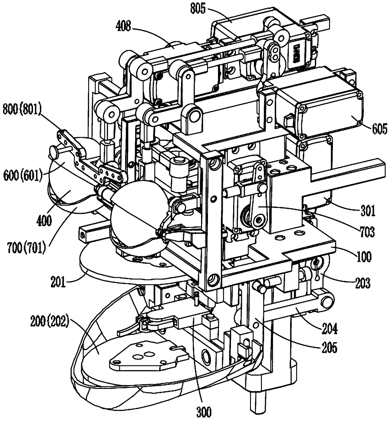
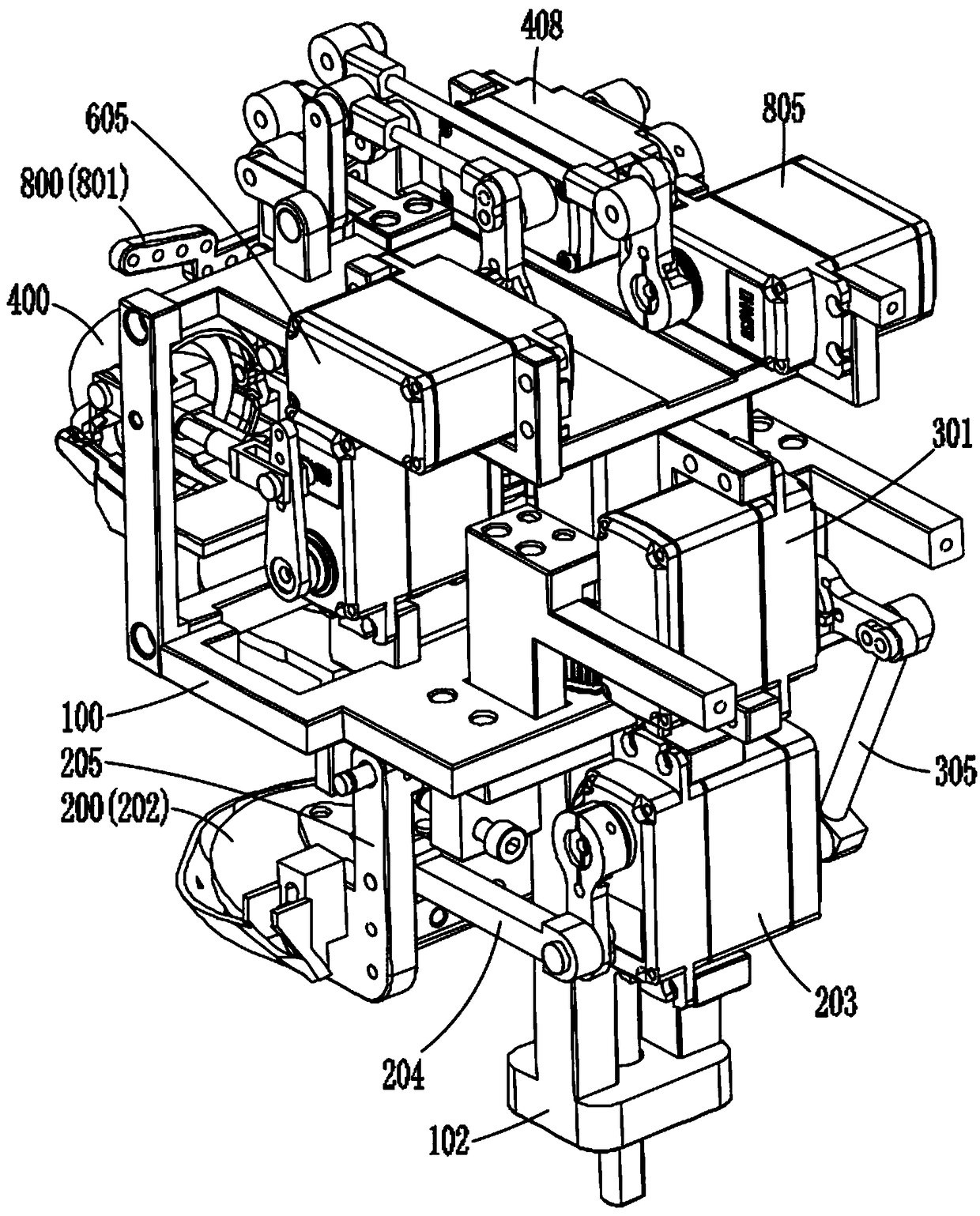
[0060] Embodiments of the present invention will be further described in detail below in conjunction with the accompanying drawings and examples. The following examples are used to illustrate the present invention, but should not be used to limit the scope of the present invention.

[0061] In the description of the present invention, unless otherwise stated, the meaning of "plurality" is two or more; the terms "upper", "lower", "left", "right", "inner", "outer" , "front end", "rear end", "head", "tail", etc. indicate the orientation or positional relationship based on the orientation or positional relationship shown in the drawings, and are only for the convenience of describing the present invention and simplifying the description, rather than Nothing indicating or implying that a referenced device or element must have a particular orientation, be constructed, and operate in a particular orientation should therefore not be construed as limiting the invention. In the descrip...


PUM


Abstract

The invention discloses a robot face structure and a robot. The robot face structure comprises a supporting frame and a mouth simulation mechanism, the supporting frame comprises a bottom plate and arear supporting frame, and the bottom plate is fixedly connected with the rear supporting frame; the mouth simulation mechanism comprises an upper jaw part, a lower jaw part, a mouth driving steeringengine and a mouth connecting arm, the upper jaw part is fixedly arranged on the bottom plate, swing plates are fixedly arranged on the inner side of the lower jaw part, a horizontal inserting shaft is arranged on the tops of the swing plates, an inclined groove is formed in the bottom plate, the horizontal inserting shaft is movably arranged in the inclined groove, the mouth driving steering engine is fixedly arranged on the rear supporting frame, one end of the mouth connecting arm is hinged to the middle part of each swing plate, and the other end of the mouth connecting arm is hinged to asteering engine swing rod of the mouth driving steering engine. According to the mouth simulation mechanism, actions of the mouth opening and closing of a person can be accurately simulated, the simulation effect is high, so that higher requirements can be met; moreover, the whole structure is simple in principle and easy to realize, and the failure rate is greatly reduced.

Description

technical field [0001] The invention relates to the technical field of robots, in particular to the technical field of bionic robots, and in particular to a robot face structure and a robot. Background technique [0002] Bionic robots are robots that can imitate living things and work with biological characteristics. Bionic robots can provide many convenient services for human beings. Therefore, more and more people pay more and more attention to bionic robots, and they have good development prospects. [0003] In order to make the bionic robot simulate the characteristics of living things more realistically, the bionic robot is usually equipped with a head structure, which can easily simulate the actions of the living thing such as blinking, opening the mouth, turning the head, bowing the head, etc., while the mouth opening actions of the existing bionic robots are mostly For the simple opening and closing action, the mouth simulation mechanism used to realize the mouth ope...

Claims


Application Information

Patent Timeline
IPC IPC(8): B25J9/08
CPCB25J9/08
Inventor 刘建斌
Owner 沧州菲漫电子科技有限公司
Why Eureka
Try Eureka