Speed-locking friction pendulum damping support

A speed-locking, shock-absorbing bearing technology, applied to bridge parts, bridges, buildings, etc., can solve the problems of weak shock absorption and inability to perform full-displacement shock absorption, so as to avoid impact, meet normal displacement requirements, and have a simple and reliable structure Effect

Active Publication Date: 2018-11-16
CHENGDU XINTU TECH
View PDF12 Cites 0 Cited by
  • Summary
  • Abstract
  • Description
  • Claims
  • Application Information

AI Technical Summary

Problems solved by technology

However, it has a shortcoming that height changes will occur in the process of normal compensation displacement. Even if the normal displacement and seismic displacement are separated by a certain structure so that there will be no height change under normal displacement, there will still be There is a section of displacement space in the lower bearing plate with no or weak shock absorption performance (that is, the normal displacement area), that is, under the earthquake state, it is necessary to complete the displacement action in the normal displacement area first, and then perform the earthquake displacement, and the full displacement cannot be performed. Displacement shock absorption

Method used


Image

  • Speed-locking friction pendulum damping support
  • Speed-locking friction pendulum damping support
  • Speed-locking friction pendulum damping support

Examples


Embodiment 1

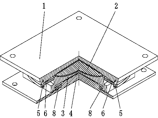
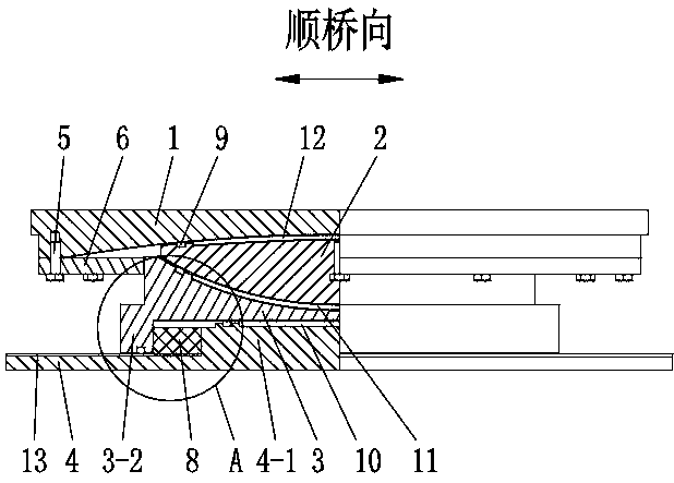
[0032] Such as Figures 1 to 7 As shown, a speed-locking friction pendulum shock-absorbing support includes an upper support plate 1, a spherical plate 2, a middle steel plate 3 and a lower support plate 4 from top to bottom, and the upper support plate 1 is used to connect with the bridge body connection, the lower bearing plate 4 is used to connect with the pier, the upper end surface and the lower end surface of the spherical panel 2 are spherical, the upper end surface protrudes upwards, and the lower end surface protrudes downwards, the horizontal projection of the spherical panel 2 is circular, and the upper end surface The lower end surface of the bearing plate 1 matches the upper end surface of the spherical plate 2 and the radius of curvature of the two is the same, the lower end surface of the upper bearing plate 1 is sunken upwards, the upper end surface of the middle steel plate 3 matches the lower end surface of the spherical plate 2 and both The radius of curvatu...

Embodiment 2

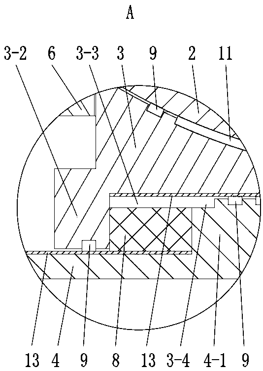
[0038] Such as Figures 2 to 6 As shown, on the basis of Embodiment 1, during the initial installation, the top surface of the speed lock layer 8 is lower than the bottom surface of the installation groove 3-1, so that the deformation filling area 3-3 is formed above the speed lock layer 8, and the deformation filling area 3-3 is formed. The area 3-3 surrounds the middle steel plate 3, and the deformation filling area 3-3 belongs to the installation groove 3-1; further, additional grooves 3-4 are provided on the boss 4-1, and the additional grooves 3-4 are located on the boss 4 -1 outside the top and communicates with the installation groove 3-1, the additional groove 3-4 expands the size of the deformation overflow area 3-3 in the horizontal direction, and the additional groove 3-4 is along the top outer edge of the boss 4-1 Setting; when there is a normal displacement between the middle steel plate 3 and the lower support plate 4, the installation groove 3-1 of the middle st...

Embodiment 3

[0040] On the basis of Embodiment 2, there are through holes along the bridge (not shown in the figure) and through holes (not shown in the figure) in the boss 4-1, and the two through holes are horizontal , the through hole along the bridge is used to connect the installation groove 3-1 area on the front and rear sides of the middle steel plate 3, and the through hole on the cross bridge is used to connect the installation groove 3-1 area on the left and right sides of the middle steel plate 3; when the middle steel plate 3 and the lower support When there is a normal displacement between the seat plates 4, the installation groove 3-1 of the middle steel plate 3, the groove wall 3-2 slowly squeezes the lock layer 8, and the shear thickening material in it deforms slowly, and moves along the bridge to the through hole and the cross bridge. The through hole can further effectively provide a place for the deformation of the shear thickening material, and the shear thickening mate...


PUM


Abstract

The invention relates to the technical field of bridge installation, and discloses a speed-locking friction pendulum damping support. The damping support comprises an upper support plate, a sphericalpanel, a middle steel plate and a lower support plate; the upper end face and the lower end face of the spherical panel are both spherical, the lower end face of the upper support plate is matched with the upper end face of the spherical panel, and the upper end face of the middle steel plate is matched with the lower end face of the spherical panel, the bottom of the upper support plate is fixedly provided with baffles through anti-shearing bolts, the baffles are horizontally arranged around the middle steel plate, and the inner ends of the baffles are in contact limit with the outer end faceof the middle steel plate; a mounting groove is formed in the lower portion of the middle steel plate, a boss is arranged on the upper surface of the lower support plate, and the boss is arranged inthe mounting groove; the bottom of the mounting groove is in plane contact fit with the top of the boss; a circumferential communication cavity is formed between the outer end face of the boss and thewall of the mounting groove and is used for being provided with speed locking layers; the speed locking layers are in contact with the groove wall and the boss respectively, and the speed locking layers are composed of shear thickening materials. During normal displacement, a lifting phenomenon does not occur, and the damping support can conduct full-displacement damping under an earthquake state.

Description

technical field [0001] The invention relates to the technical field of bridge installation, in particular to a speed-locking friction pendulum damping support. Background technique [0002] Nowadays, there are many kinds of shock-absorbing bearings for bridges, such as high-damping rubber bearings for roads, lead-core rubber bearings, friction pendulum bearings for highways and railways, and E-shaped steel bearings, all of which have significant shock-absorbing effects. [0003] The shock absorption principle of the friction pendulum bearing consumes frictional energy through the conversion of kinetic potential energy. However, it has a shortcoming that height changes will occur in the process of normal compensation displacement. Even if the normal displacement and seismic displacement are separated by a certain structure so that there will be no height change under normal displacement, there will still be There is a section of displacement space in the lower bearing plate ...

Claims


Application Information

Patent Timeline
Patent Type & Authority Applications(China)
IPC IPC(8): E01D19/04
CPCE01D19/047Y02A30/30
Inventor 骆明成陈宏黄菲
Owner CHENGDU XINTU TECH
Why Eureka
Try Eureka